Fault finding CDI ignition Aprilia Leonardo

A week back we had a very violent thunderstorm. It blew up a laptop PSU (fuse blown) but the oddest one is that my scooter got blown over and when I tried to start it wouldn’t fire. Thought it was low fuel but after top-up of the tank and a lot of cranking it was pretty clear I had more of a problem. The rest of this post details how I fault-found this problem.

The ignition system for this generation of bikes is fairly simple consisting of a TDC sensor in and an output to the ignition coil primary (plus 12 V and ground).

When the ignition  key is turned on then this provides 12 V to the CDI and to one leg of the ignition  coil primary. The other leg of the ignition coil primary goes back to the CDI unit. To fire the coil the CDI unit applies and removes ground to this primary coil leg. So a high current pulse then flows through the primary which energizes the primary coil, which is then multiplied in voltage by the ratio of windings to the secondary coil, the pulse of electricity is then discharged through the ignition  leads through the spark plug to the engine ground. The CDI knows when to fire because a coil pickup on the flywheel tells it when it is TDC.
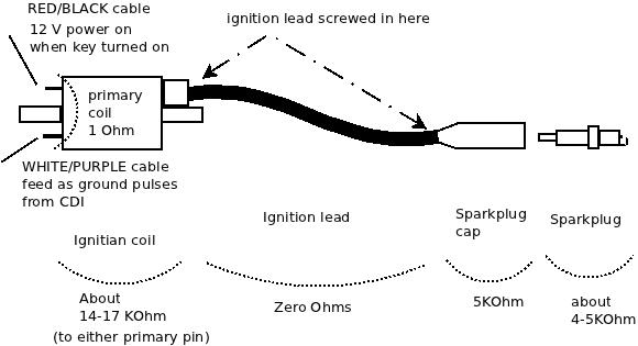
Checks – Ignition Coil and Sparkplug

The ignition primary coil is easily checked. Looking at the coil (on the right hand side of the bike under the inspection panel), it has a RED/BLACK cable to the key, a WHITE/PURPLE cable to the CDI, a fat black cable to the sparkplug.

To stabilize the very high voltage secondary coil pulse  the sparkplug cap and the sparkplug are resistive. The cap is 5 KOhms and the sparkplug is also about 4-5 KOhms. The ignition lead is screwed into both the  ignition coil and the sparkplug cap. The coil and plug has what looks like a woodscrew poking out deep inside hidden in the coil or plug and you screw the ignition lead onto that point. The ignition lead cable can and will on older bikes have internal damage in its conductors near where the lead screws in if the cable is old. If you remove the sparkplug from the engine then click it back into the sparkplug cap then you should see about 25 KOhms from the centre electrode in the tip of the sparkplug back through to the primary coil (the primary and secondary are joined on one leg and it is only 1 ohm between the primary coil). If you do not then check the spark plug has about 4-5 KOhm resistance from its centre electrode in the tip to the small threaded end. If it doesn’t e.g. it is open circuit then replace that sparkplug and hopefully that is your only problem.

If it is OK then unscrew the ignition lead from the ignition coil secondary. Now measure the ignition coil secondary from the screw tip that you can see poking out to the primary coil tabs. If this is not about 17 KOhm but open circuit then you have a broken ignition coil but if it is a few KOhms then check the part is the same – secondary on ignition coils can be different. You really only care about shorts i.e. zero Ohms or open circuit i.e. infinite KOhms. Replace this if it is clearly broken.

If this is OK then measure from the ignition lead core wires (which you can now see on the end you unscrewed from the ignition coil) to the sparkplug cap.  It should be about 5 KOhm. If not then unscrew the sparkplug cap from the ignition cable. It has a similar woodscrew deep inside it that you screw the ignition lead onto. The cable is a multi-core of fine wire and it may have frayed and broken internally. Measure its resistance and it should be zero ohms. Wiggle the cable –  internal breaks can be felt as a soft section that more easily moves than the rest of the cable. If the cable is OK then measure the sparkplug cap and it should be 5KOhm. If it is not then replace this. If that is OK then you are disturbing the break that you originally detected and it is probably in the cable where it screws in to the coil or sparkplug cap. You may have enough spare lead to cut off the end to get to unfrayed core wires, if not then you need some new ignition cable.
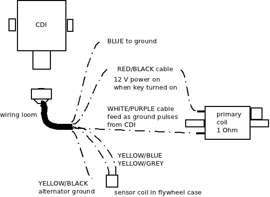
Checks – CDI

In my case I did all that but it wouldn’t fire.  Now you will have to remove the bike body covering to get at the CDI. I won’t describe that but you basically remove any helmet carrier on the rear, remove the read handhold, unscrew the rear light cluster, license plate holder, undo all the little screws under the seat, the big screws towards the lower front near the feet-stands and then slide the body panel back as one big mass. The CDI is on the right hand side with a 6-pin cable plug.

Unclip this and do the following checks by poking your multimeter probes into the socket,

  • BLUE is Earth – make sure it is and is zero ohms to the YELLOW/BLACK
  • WHITE/PURPLE goes to the Ignition coil primary – check it is zero ohms to that coil and that when the RED/BLACK is removed from the coil primary, that there is no shorts to ground or the RED/BLACK socket (here)
  • RED/BLACK goes to the 12VDC keyed off the ignition same as the power to the coil – so should be zero ohms to the battery positive.
  • YELLOW/GRAY goes to one side of the TDC sensor coil – there should be about 240 Ohms resistance between this pin to the YELLOW/BLUE
  • YELLOW//BLUE goes to the other side of the TDC sensor coil – see the YELLOW/GRAY cable.
  • YELLOW/BLACK is Earth so should be zero ohms to the engine frame.

If all those seem to be right then you are pretty well  left with one conclusion and that is the CDI itself is not working. This is fully sealed and cannot be repaired. Your best bet is to buy one second hand. Make sure you get the exact DENSO part number.

In my case the faulty unit had the WHITE/PURPLE signal which goes to the ignition  coil primary was always on as a ground signal. It should never be always on but pulse a ground. I can only guess it was shorted out inside the CDI. All that happened was that the ignition  coil would heat up.

Checks – firing sparkplug out of engine (caution)

This is a more dangerous check but I’ll include it for completeness. You can see if the sparkplug is sparking as follows,

  • remove sparkplug from engine and click back into the sparkplug plug. Feed the ignition lead and sparkplug to the right-hand side of the bike away from the open engine sparkplug hole and so you can see the spark when you fire ignition switch
  • Ideally fit a spare sparkplug into the engine sparkplug hole BUT if you do not then you must do this testing outside because petrol mist will leave the engine so you want a lot of ventilation
  • use a jumperlead to connect the sparkplug screw thread to the engine body. I use a battery jumper lead as these are very low resistance.
  • turn on the ignition and try to crank engine. You should see a bright blue-white spark pulses even in daylight. If you do then your starting problem is not ignition but perhaps fuel. If you get only ONE spark when the ignition is turned on then you have my problem of a shorted out CDI. If you get NO sparks then assuming your test setup is fine and you have tested all the other components then it is the CDI with a faulty open circuit.

Enjoy your bike riding !

Microwave oven wiring fix for scooter wiring

The wire on the temperature gauge of my Aprilia Leonardo finally broke near the socket so the temperature reading stayed on low/no reading. If you look you can see a metal pin on the gauge that the needle sits against. After about 2 minutes of motor operation the needle should move off that pin. If it doesn’t then check that wire.

To do this ideally remove the right-hand side inspection panel and the temperature sensor is towards the middle bolted into the engine block around the same level as the starter motor (the oil pressure sensor is much lower).

This can both come loose (mine did a year before) or finally snap off at the plug. The temperature sensor has a spade plug end on it so nothing special but you don’t have any slack to play with on the wiring loom so you need an extension wire but I discovered a nice fix that will probably work for you too.

Many months ago I had picked up a junk microwave from the road side: I had pulled it apart to see what was inside and I remember keeping all the wiring looms from the microwave. The wiring loom connects all the microwave door interlock switches together to the control board. Looking around for suitable wire to repair the bike I noticed that the microwave loom had these nice sockets with moulded plastic covers and reasonably good sized cable. The cable lengths are only a short distance of a few inches/centimetres but that’s all I needed.

I tried one of the sockets fitted the temperature sensor on the bike and it clicked on perfectly. So I chopped off one of the sockets with about 3 inches/8 cm of wire on it, stripped back the end and then stripped back the end of the broken wire on the bike, cleaned the corrosion away and then used a barrel/coupler connector to join the new bit of ex-microwave wire to the bike wiring loom wire.

It worked.

Idea: using sound to detect engine problems.

I found a problem with splits in the rubber coupler that connects the carburettor to the intake manifold of an Aprilia Leonardo 125 ST (year 2001) and it struck me that given the sound of the problem that an expert system could have identified this problem quicker and quite automatically.

I’d initially thought it was valve gap but checked that but still had a problem whereby the acceleration and top speed seemed fine but it sounded a bit throaty with backfiring at low revs and it would stall when parked at idle (especially hot idle).

I was also fixing the starter motor at this time and that’s located under and near the carburettor and I’d wiggled the carburettor and noticed the coupler seemed to be twisting. I then ran the engine and forced the carburettor in so that any gaps in the rubber coupler would be closed and it started to idle fine – moved the carburettor back (thus opening the splits) and the engine stalled.

So that was my fault solved – bought a new coupler, installed and all my problems gone.

Now an experienced mechanic could probably recognise this sound and point to the problem but there is a fundamental problem with that approach in that it takes time for a mechanic to become an expert and as vehicles get rarer then this knowledge disappears and certainly when the mechanic dies then this knowledge is lost forever.

A library of the sounds of the failing machinery coupled with the expert interpretation and actual real-world solution in some central database would provide an interesting corpus in which a user provided sound sample could then be analysed against this library of sounds and the possible problem and solution could be offered. Imagine holding your phone up to your car or bike engine or other mechanical device and then sending the photo and sound sample to some central server, which then breaks it down e.g. using a FFT to get a spectrum and a time series and then seeing what matches the library of samples.

It shouldn’t be as hard as speech recognition but it should be a similar workflow in the computations.

This would not remove the need for the mechanic – someone still will have to source the part, replace it and potentially tune it and this would still be hard and messy. Such a system would allow a skilled mechanic who can remove and replace parts fast to work on engines that they normally would not have much experience with because they would have the problem already diagnosed by others.

This also is congruent to the Open Source community if the software was open source in that non-mechanics such as me who like to work on our own vehicles could sample and upload the sounds and the solution and so, in the same creative commons way, build up the expert system so that everyone can benefit.


Side effects of fault voltage regulator on Aprilia Leonardo 125 ST

About 6 months ago the voltage regulator failed on my Aprilia Leonardo 125 ST (2001) but I’m now confident that it was playing up before that time.

I’ve had the bike for 3 years with no problems and then the battery failed earlier this year. I assumed it was just old and so bought a new battery and it was working well for a few weeks until one day I came home and smelt boiling acid. This brought back memories as I’ve worked on very large battery banks (up to 10,000 AH at 50VDC for TELCOs) and so recognised that acrid smell of heavily working batteries.

I carefully popped the seat open and removed the battery cover. Acid steam was venting. I got water, goggles and gloves and unbolted the battery and removed it. Beh ! brand new battery cooked. The next day I re-charged the battery, put it back in the bike and it seemed OK but I doubt it would last.  Everything seemed fine though with an expected battery voltage.

I’ll jump to the end and what was happening was that the voltage regulator was failing but only intermittently. It eventually failed long enough for me to see a reading of 17 volts on the battery terminals !

The side effect of this though was the following…

  • the headlights would run normally and then would run brighter. I drive with the lights on all the time and so the higher voltage meant that they drew more current and this both contributed to them blowing faster and drawing more current through the light switch. I’d noticed this but never really thought much of it. I’ve blogged about the switch failure here.
  • when the battery failed then I had trouble starting the bike and so this meant more cranking. This probably contributed to increased wear on the starter brushes. I blogged this here.
  • the increased voltage meant an increase in current overall for all systems and so this probably helped the ignition switch to also slowly unsolder itself. I’ve blogged this here.

So: if you notice your lights altering in intensity a bit, or the radiator fan changing sound/speed, or certainly if  the battery is getting hot then you must check the voltage on the battery terminals is precisely as expected (which is usually under 14 Volts).

With intermittent problems there is not really much you can do because there are no engine management system over-volt indicators on such an old scooter so you just have to be alert for these subtle indications in the lights or fan sound before you end up with a boiled battery and a whole pile of other electrical problems.

The voltage regulator is the same across a wide range of Aprilia bikes so the part can be bought fairly cheaply second hand or you can invest in a new one. Once I put a new regulator in then I replaced the battery as the cooked one couldn’t be relied on.


Aprilia Leonardo 125 loss of ignition due to faulty switch

On my Aprilia Leonardo 125 ST year 2001 scooter, about the same time that the starter motor was playing up, the ignition would fail. I initially thought this was all interrelated but it eventually stopped all together i.e. the dashboard lights would be off (no oil pressure light and no indicators) plus the headlights stayed off and the starter relay wasn’t working. It was dead.

I proved where this was quite easily once I had a multimeter. The 12 volt feed goes from the 20 amp fuse in the battery box through the wiring loom to the ignition switch. To get access to this you need to…

  1. remove the front fairing as if you were accessing the radiator
  2. remove the protective trim parts that are on the edges of the internal shield above the mats. These are held on by 3 large hex bolts
  3. loosen the front shield so that you can get inside the area behind the shield

The ignition key and switch is on the right hand side of the bike and has a long cable about 30 cms that goes to a plug. If you unplug that plug then you can test the switch operation. It is very simple on the 2001 model – no fancy electronics. The 12 Volt comes from the fuse, goes through the switch and back to the rest of the electrical system and the fuse box.

If you set the multimeter to continuity or resistance  then when they key is in the ignition on position then the switch should be closed and show a short i.e. zero ohms on that plug. Mine wasn’t – the switch wasn’t closing.

This switch is not easily field-repairable because the cables are soldered in the switch. If you want to get home then you need to simply short the socket that comes up from the wiring loom. This (in effect a “hot wire”) will work and you can get home or to a garage.

When you are home then you can inspect the ignition switch. It is in two parts – the key part which is fixed permanently to the frame and cannot easily be remove and the electrical switch part which is removable. There are two screws that hold on the plastic electrical switch but they are hard to reach. You will almost certainly have to unbolt the horn and move it up and aside to get room.

Note that you cannot use a screwdriver but must use a screw bit with adapter in a small (1/4″) ratchet wrench tool. If the radiator looks like it is in the way then it may have jumped out of its mounting – mine was (the rubber bush on the top was broken).

Once the switch is out then mark the position of the switch with a CD marker pen and pop it open. It has the usual plastic locking tabs that pop into holes so easy to carefully pull apart. What I found on mine was that the contact had heated up so much that one of the wires had un-soldered itself.

I carefully trimmed the wire and re-soldered it back into the hole. I then also sealed it in place with High Temperature Silicon sealant (red or orange) and then reassembled, screwed it back onto the ignition key switch, bolted the horn back into place and it is all working fine. Note that I initially had not used sealant and the other wire came lose about a year later. Ideally if you use sealant it should all stay in place.

I’ll post another post that brings the three problems I have had together i.e. headlamp switch faulty, starter commutator worn and ignition switch faulty as I think they are related to something that happened 6 months ago when the regulator failed.

Dead spot on Aprilia Leonardo starter motor

Another electrical problem but I found out how to prove this and discovered a very useful get-you-home fix; The problem is that I tried to start the bike but just heard the click of the starter relay.

The quick answer to what I eventually found was that the brushes in the starter motor had worn down to the last little bit (on 43,000 kms). Minor variations in the commutator meant that the brush did not touch at one point. It had a “dead spot”.

I discovered a get-you-home fix; Turn on the ignition and push the starter switch then bounce hard up and down on the seat (like you are testing the shocks). This rotates the starter motor around a little to step over the dead spot if it is a dead spot and it may start – it did for me.

If that fixes your problem then get to a garage or home in one go because what it means is probably that your starter bushes are down to the last bit of metal and this will fail to start again and the bouncing on the seat trick may not work.

As I mentioned I accidentally discovered the temporary fix but in proving what was actually wrong I also worked out a test routine as it could be one of 4 different things,

  1. the relay contacts not working
  2. no 12VDC +ve in
  3. no Earth
  4. problem with starter motor

When you push the ignition switch then you should hear a solid click of the relay every time you push in the switch. The relay is located under the right hand side of the seat and the contacts are visible through an air vent just above the right hand inspection opening. They are two large lugs.

If you don’t hear this click then you have a problem with the relay circuit from the starter switch on the handlebar to the relay. You’ll have to trace this out with a multimeter though if you are on the road and don’t have a multimeter then I would,

  • Check fuses are OK
  • check wiring connections to relay and to starter switch look ok (no corrosion)
  • check starter switch making contact (if you can you could try to prove by shorting the switch contacts with a wire)

If the relay is making a click and if you don’t have a multimeter you can test (1) and (4) by shorting the contacts of the relay with a bit of wire. Don’t short to frame – just between the contacts. One side is always 12V +ve and the other connects through the starter motor to the engine earth. With the ignition OFF if you try and short the relay contacts and they do NOT spark then the starter motor (or Earth or +ve supply) probably has a problem. If they DO spark then the relay probably has a problem. Take care with shorting this obviously.

If you do have a multimeter then testing is very easy. You should see 12 volts on one side of the relay all the time and when you push the starter switch then it should appear on the other side.  If it does not then the relay is probably faulty.

If you do see the relay working then the 12 volt supply goes to the starter motor via the heavy cable (then through the motor to the earth). With the ignition off then if you measure the resistance from the battery -ve/Earth post to the starter relay lug that goes to the starter motor (not the other side of the relay as that is always live !) then you should see less than an ohm e.g. only half an ohm (0.5 Ω) – basically a near short as the starter motor is about 500 watts so at 12 Volts that means about 0.3 ohms. If you see a high reading (more than an ohm) or an open circuit then check that the case of the starter motor is low resistance (it should be at earth) and then check that the lug into starter motor is low resistance. The starter case will be corroded a bit so make sure you are touching actual metal.

If your finding is that the starter motor has a high resistance through it then it is probably the brushes. The starter motor is easy to remove though it will clash with the carburettor so not much wiggle room. The starter motor is also easy to pull apart and if it is a worn brush then this is obvious. You may be able to get a few more starts by bending the brush housing a bit but the brush wire is what will stop you in the end. If you do bend the housing to gain some starts then you can test the motor on the bench by checking the resistance stays low between the case and terminal lug whilst you slowly rotate the motor by hand one whole revolution. It should stay low ohms at every point.

If it is an original Mitsui starter motor then I don’t believe that you can get replacement brushes assembly though an auto electrician may know of an equivalent brush part. AFAIKS the starter motor is the same for all  Leonardo 125 and 150 models for all years (96-04) and for some other models that use the Rotax Type 120/154 (120S-154S) engine (e.g. Scarabeo 125/150/200 from 99-03 and also the BMW C1 125/200 from 00-03 ). The OEM Aprilia starter motors are very expensive – but there are much cheaper “Economical” or equivalent motors that are made that are a 1/4 of the price new. Unless you know the kilometres of a second hand bike or you can actually see the bushes to see how much is left on them I wouldn’t buy a second hand starter motor.


Aprilia Leonardo 125 head light switch repair

And now for something completely different but this uses electricity so thought I would add it here; Front lights stopped working on a 2001 Aprilia Leonardo 125 (ST). The fix worked out to be rather easy: There is no relay with this – it is wired from an ignition supply through the right-hand light selector to the left-hand high/low beam switch and then down to the headlights.

To test this you need to remove the back of the display console like you would do to top up the brake fluid (i.e. you would have to remove your windsheild/windscreen as well if you have one).

If you look inside where the right-hand side controls are you have the starter motor switch on the bottom and the light selector above it. The Light selector is in two parts each with 3 pins; the top of the switch is the main lights and the bottom is the back and front side light (which is a small light in the middle of the front light cluster). For the main beam section it has a green supply wire and a black/yellow wire that goes across to the left hand side high-low beam selector. There will be regional variations with this switch but they should function the same.

With the ignition on then you should get 12 Volts on the green supply wires and when the switch is moved to the on position then the 12V should appear on the other pin.

With mine it wasn’t so I remove the switch; to do this there are on the back, a tab on each side of the switch towards the top which you need  small flat screwdriver to push in and so can now push the switch out. The switch comes out and up as a complete assembly.

There may be newer models that are all sealed but with mine the dismantle was easy – on the back of the switch there is a section that pops down and you can now take out the inner red spacer and then slide out the switch lever. My fault was obvious; over time the switch has heated up and the plastic of the switch has melted and has stopped the switch contact from staying in contact. Cleaned out plastic with a knife, bit of plain grease, reassembled, tested and installed and the lights worked.

Second hand (or even new) this part is quite cheap so why bother with a repair ? The problem is that the bike isn’t street legal without lights so if it can be fixed without having to hunt for replacement parts then your downtime is reduced.  While you are at it, if it hasn’t been done, you can do your brake maintenance given you have the master-cylinders exposed.