Toshiba Satellite R630 power button replace.

This is reasonably easy but you will have to take off the whole underside/back/bottom plate of the laptop. A client managed to break the power button on their Toshiba R630-141 laptop. The button is a single plastic part that consists of the button, a plastic spring leaf and a complex base.

With the screen shut, and upside down, remove the battery (and the power and any other cables if still plugged in). On the underside (base) , unscrew all the screws. There are two main sizes of screws but the short ones have a tiny “F4” printed near them on the case so not too much of an issue if they are mixed up with the longer screws. Remove the 3 cover plates (hard disk, memory and an unused docking port). The back cannot come off until one of the screws under the hard disk cover plate is also removed (it is obscured by the cover plate). Remove the hard disk by lifting the disk up and unplugging its SATA socket. This is attached to a ribbon cable and it has a plastic backed cushion. I did the hard disk removal too but I don’t think it is really necessary. If you do not remove the hard disk then note that the hard disk has no other clamp so be careful it doesn’t fall out and dangle from its ribbon cable when you are looking at the power switch from the front panel.

The whole base should now be removable but you will have to lift the DVD side first to then clear the sockets from the plastic holes on the USB port side. If it isn’t lifting then you may have forgotten a screw. You should now have the back removed and will see the hinges. The power switch is near the power socket. You will have to…

  1. remove the screw that holds that hinge down,
  2. lift up the hinge (it is very stiff but you can do this by your fingers) to clear the plastic cable guide,
  3. ease out the cables (twin, grey and black) and remove the plastic cable guide,
  4. remove the power socket (its cable unclips and it slides up)
  5. unscrew one silver screw that is closest to the power socket on the CPU board and another that is diametrically opposite on this board (these two screws loosen the power/CPU board).

This will allow the CPU board power socket edge near the radiator grills to be lifted up enough (at least 1 cm) to remove and replace the power switch plastic parts that are hidden underneath it.  The power switch button is not screwed in but the plastic casting has guide holes and a plastic spring clip. It is fed down, with the guide pin keeping it in alignment, and then the plastic spring clip clips into the front cover plastic with a firm click. You should see that the button is correctly in its hole (which is what you push from the front).  You can carefully open the front cover to see that the power switch is correctly seated.

Reassemble in reverse order,

  1. Blow out any dust on the base cover. It will have significant dust on the grill
  2. add the CPU board screws (2x)
  3. add the Power cable and socket
  4. add the Cable guide, feeding the twin cable into guide
  5. Push back the Hinge onto the cable guide (it will be stiff) and screw to clamp down cable guide
  6. Refit the hard disk and its plastic backed cushion if you had removed this.
  7. Refit base, click in the USB socket side first. Check no gaps or pinched cables
  8. Re-Install all screws, remember F4 screw holes are the short screws
  9. Reinstall all cover plates

The laptop is now repaired. Reinstall the battery, and power up. Keep an eye on things you may have disturbed such as, CPU cooling, memory sizes, WIFI signal strength, DVD operation, audio jack.

The power button replace should take just over one hour.

Fixing the Western Digital excessive load/unload problem with idle3-tools

I have an always-on machine (self made Ubuntu 16.04 based using retail parts) that is lightly loaded in CPU but is continually writing to the hard disks. I recently added a Western Digital 2TB drive ( WDC WD20EZRZ-00Z5HB0 ) about 2 weeks ago (368 hours) and noticed that the Load/Unload cycles was over 30,000.
The other two drives, both WD Blue 1TB ( WDC WD10EZEX-08M2NA0 ) showed up with less than 100 on 15,000 hours so something was very wrong with this new drive in my system.
The fix is to adjust the wdidle3 setting from its default of 80, which means 8.0 seconds, to a bigger number such as 129, which means 30 seconds.

The number on newer drives is not just divided by 10 but is staggered scale so 1-128 is divided by 10 but 129-255 is in 30 seconds increments (129 = 30sec, 130 = 60sec and so on) for newer drives but it is just divided by 10 for older drives. I do not know what is deemed new or old manufacturing date for WD drives.

You can read and set the wdidle3 parameter using hdparm -J option but it has a very cautious warning message as the option is experimental.

You can read the S.M.A.R.T value for the Load/Unload using smartctl from the command line, (or GSmartControl using a GUI) and the ID is 193 thus,

sudo smartctl -A /dev/sdc | grep "^193"

I get…

193 Load_Cycle_Count 0x0032 190 190 000 Old_age Always - 31283

where the 31283 is my current, but now stable, excessive count.

To set the parameter I downloaded and used the idle3-tools from http://idle3-tools.sourceforge.net/ This is a small program that you just untar and make or you can install it with,

sudo apt-get install idle3-tools

I set my drive with…

sudo idle3ctl -s 129 /dev/sdc

…which for new drives means 30 seconds ( and -s 130 would mean 60 seconds and so on) . After you set the value in the drive you must turn off the power to your computer (drive) as the value is read at power up. So do a shutdown and then power off.

I have no idea why Western Digital do what they do but it is not that friendly unless you delve deep. Reading the WD support forums the problem is from many years ago and is still taking place today. I expect to be able to install a disk and not have it artificially age itself but adapt to the load. Equally I have no idea yet if the 30 second value I have set is a better compromise. It has stopped the value increasing and if my programs stall then the disk will unload reasonably early.

Acer Aspire ONE no WIFI in Ubuntu due to hardware switch state

Intermittently when an Acer Aspire ONE suspends in Ubuntu 14.10 then the WIFI does not come back. The hardware switch (a non-latching slider switch on the front right hand side of the laptop) has no effect. Rebooting and disabling/enabling Networking has no effect.

The rfkill list command will show,
0: phy0: Wireless LAN
Soft blocked: no
Hard blocked: yes

One way I found to clear this is to power down the laptop and then hold the WIFI switch to the right i.e. in the on position and then use the power switch to turn on the laptop as normal but keep the WIFI switch held on. You should see the little orange WIFI  LED blink once and once the laptop is starting to boot up after the BIOS display then release the WIFI switch so it flips back to the left/off position.

The WIFI should be back to normal now and the rfkill list will show Hard blocked: no.

ASUS X51R laptop CMOS battery bad causes blank screen no boot

The ASUS X51R laptop exhibits a strange failure when its built-in CMOS battery is dead or low. Rather than having some kind of fall-back it basically ceases to operate from power-on. In some cases it will post a message about CMOS battery low but when you continue then it stays on a blank screen and doesn’t boot. Most of the time it will just power to a blank screen i.e. the laptop seems to startup and have fans and disk startup but no further POST or booting into the operating system. The “Zz” light may be on all the time but that is not relevant.

A client got this problem – one day it was booting fine and the next it was a blank screen so there is no early warning of impending failure.

The CMOS battery is a 3 Volt CR2032 style battery. These last for around 7 years so always keep them in their packaging so you can see the expiration date. Ideally use a new battery from a trustworthy supplier for a client laptop as it takes a long time to replace.

To change the CMOS battery you need to do a complete tear down of the laptop to the motherboard. There is nothing unusual with this teardown – if you have never stripped a laptop then this is not a job for you. I have done a lot so this was pretty trivial tear down,

– remove main battery, memory, hard disk, and WIFI
– remove all visible screws on bottom and back (they are all different sizes so draw a picture and keep them in separate piles),
– push in the 3-tabs at top edge of keyboard and lever out keyboard (unclip ribbon cable),
– lay screen fully back and lever up plastic covers on screen hinges and the curved plastic cover that is in the middle that is over the screen cables to motherboard plugs
– unclip the screen cables from the motherboard and flip over and unclip the WIFI cables and poke the wires out as you remove the screen (the screen itself just stays assembled to its hinges with 2x WIFI cables and 2x multi-way screen cables attached)
– unscrew the screws that you can see that were being hid by the keyboard and that were hidden by the screen that hold the top cover down
– unclip the narrow touchpad ribbon cable and pop up the top cover,
– unscrew the screws on the motherboard – there is a arrow-head symbol near each hole that marks which holes are used but ideally draw a picture and keep the screws seperate,
– unclip the fan assembly and cable, the speaker cable (towards middle front of motherboard) and battery feed ribbon cable and remove the DVD/CD drive if it’s not yet removed (it should slide out as its retaining screw is removed),
– carefully lift out the motherboard,
– you will see the battery on the bottom – it is a standard fitting – use a screwdriver to pop in the retaining tab and then remove and dispose – remember which way it was oriented but the +ve case side should be up (-ve small disk side down),
– do not use your fingers to touch your new battery but remove it from its packaging and clean your new battery with a clean dry cloth and then insert into the socket without touching it with bare hands. The reason to not touch it is that your hands have oil on them and over many years this can corrode.
– Re-assemble in reverse order.

Before re-assembling fan then please clean out the dust. There is nothing special to remember on re-assembly.

When assembled then it will boot instantly without any problems. The date and time will be wrong (reset to 2007 or similar) but you can easily reset this. With a new CMOS battery the laptop should last for another 5-7 years. The whole job takes about 1.5 hours.

memtest86+ cannot load a ramdisk with an old kernel image

This error happens when you use UNetbootin to create an Ubuntu disk and it incorrectly adds a ramdisk to the memtest86+ boot option.

Until UNetbootin fix their code then cursor down to the “Test memory” option and hit tab and then at the boot options remove the “initrd=/ubninit” so that the command line is now just…

/install/mt86plus

and then hit enter and Memtest86+ will now run as expected.

My Ubuntu 14.04 currently has UNetbootin 585-2ubuntu1 and this quirk will possibly be fixed in newer releases but sometimes all you have lying around is an emergency install USB/disk so always good to know how to get around  a problem rather than downloading new code.

PS3 bluray not reading disks

We got a few more months out of the fixes that I did here but then disks started to not read again. I dismantled the drive as per that post (see here) but at step 8 I did some additional cleaning.

Note that the floating lens that is right in the middle of the lens mechanism shouldn’t be touched. It is very delicate. It may have dust on the lens but don’t touch this unless you really have to. If you do see some dust then use a CLEAN cotton-bud and carefully slide off any dust.

a) Use a cotton-bud and remove the built-up grease on the drive guide-rods. These are the 2 stainless steel rods about 5 cms in length, one on each side that supports the lens mechanism. They had a build-up of crud at the ends.

b) Use a cotton-bud and remove the built-up grease on the drive worm-gear. This is a single bronze gear that is about 5 cms in length and as it rotates then it moves the lens mechanism (which slide up and down the guide rods). You can rotate the worm gear and this will cause the lens mechanism to move back and forth. It will automatically reset itself so don’t worry about moving it, just get rid of any built-up crud  that stops the lens mechanism from travelling from full inner to full outer position.

After doing that (and the previous fixes) then the PS3 started reading the disks again.

Using xboxdrv on Ubuntu to fault find PS3 Playstation controller

A Playstation PS3 controller has drift on the left hand analog stick. If you have the xboxdrv installed then when you plug the PS3 controller into a linux machine and then if you do,

 sudo xboxdrv --detach-kernel-driver

in a command console and hit the PS button on the controller then the command console displays the key/stick values continuously. For my broken controller the “X1” when idle is 224 something and not 128.

Obviously you could replace the potentiometer but that’s assuming you can get the parts but you can clean and refurbish the potentiometers.

To do this unsolder just the single potentiometer from the controller PCB. It is held in by plastic tabs to the housing of the analog stick assembly so lever it out on its own.

You now have a single small potentiometer with 3 pins. The centre pin is at the 1/2 way resistance point. There should be a small plastic split pin on the centre of the tiny potentiometer that removes the rotary plastic part. I used a cotton-bud and alcohol to clean the internals of the potentiometer.

I also re-sprung the rotary part by using a pin/knife to bend up the small contact springs so that it made a good contact even when wiggled. That’s the important part – you have to test it with a multimeter and make sure it goes from 0-10 k Ohm from the centre pin to the outside pins.

On my sample controller the potentiometer was marked “103” and this mean 10 K Ohm. The outside pins are the full 10 KOhm value and the middle pin varies from 0 to 10 Kohm. I made sure it went over this range scale and stayed solid even when the centre rotary part was wiggled. A loose spring contact will mean jerky game play.

PS3 Bluray drive clean-out dust bunnies and no disk load

This is electronic related so I’m going to post this. Three different problems,

  • Right at the start of the summer holidays our children’s PS3 bluray disk drive started to play up; symptoms are spurious ejects after load and poor reading of disks.
  • Then at the Christmas holidays the disks were not loading at all and the blue load light was always on.
  • and there has also always been a problem of poor on/off switch performance.

What I did (out of warranty repair – if your PS3 is still under warranty then let the store work out the problem),

1) Slide-remove the decorative cover (to left when PS3 is lying down flat with the bluray slot to the right) and then undo the 7 screws on the top case cover (has one short size screw and the rest are long – the hole with an ‘S’ is the short screw). Push in the tab at the back right hand side and then lift off the case cover up from the back – there are a row of tabs on the front that you pivot it out of these.
2) Unscrew the PSU – it has 5 screws in total (2 longer plus 3 medium), one plug on the front, the main 230 Volts on the back AND it has a pair of blade pins hidden towards the front so just lift it UP to slide out of the socket.
3) Un-connect the Bluray DVD ribbon cable by flipping up the black locking tab and remove the white 4-wire power plug for the Bluray on the front.
4) Flip the Bluray over and remove the 2 x silver and 2 x black tiny screws.
5) Remove the metal case cover. The DVD top retainer will fall out. It is OK it’s held in by nothing but the case.
6) Note the EXACT position of the white rotary parts that you can see. Remove the two tiny black screws on the main part of the disk loader mechanism – they are towards front. Pop up the two tabs on each side carefully. This whole lot comes off.
7) Pop in the tab in the middle of the front disk loader mechanism to release this. This lifts up.
8) Clean out all the dust bunnies. Note that the lefthand rack does not touch the black cog – that’s how it is designed.
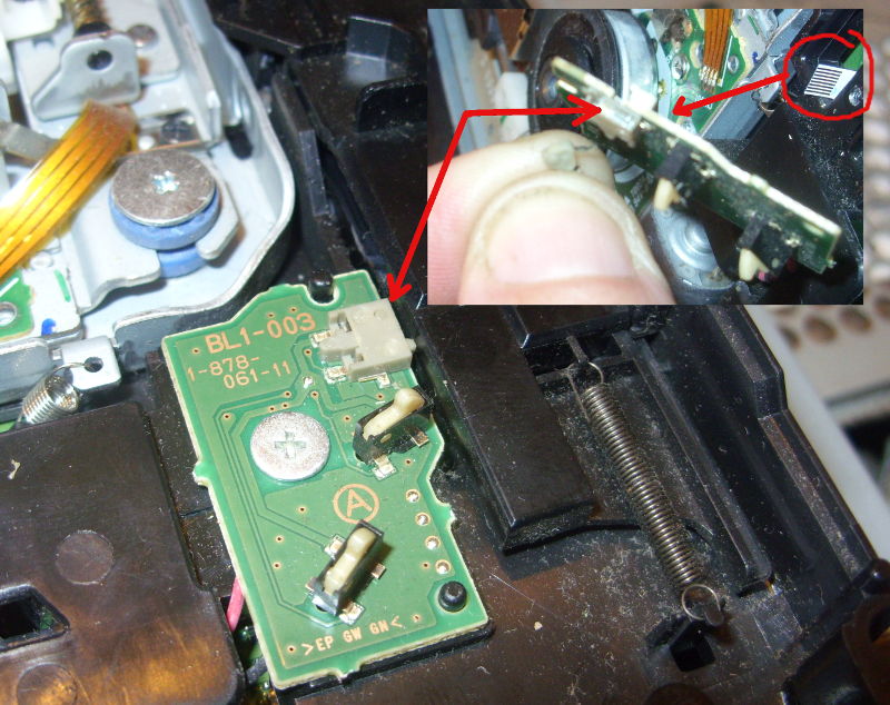
9) If disks are not loading or the blue disk load light remains on even when there is no disk in place then the right hand side has a PCB that has 3 tiny switches on it – 2 vertical that detect when disks are inserted and 1 flat that detects when the mechanism is in a ready position. Use a multimeter and check that these switches close circuit when pushed in and keep closed when you wiggle things around. The one I had fail was the flat one that gets moved by the tray mechanism. It can be dismantled and cleaned out (to do this unscrew the PCB, remove the flat ribbon on the underside, and use a finger-nail and pliers to pop out the switch lever. Clean any gunge on the back inside of the switch with a 0.5 mm solid wire e.g. wire gauge. ps3-load-sensor
10) Reassemble is in reverse BUT how the loader mechanism works is that as the disk is powered (tiny sensor switch to right) in then the left hand levers on the back part of the disk loader mechanism rotate anticlockwise as a disk is loaded and then this moves the left hand rack slider a bit so it hits the black cog. This cog then pulls the rack to the front and the slider then raises the platen. If you do not set the rotary parts right into the left hand slider then when the disk is loading it doesn’t rotate these bits of plastic so they don’t shift the slider to engage with the cog of the motor. You should be able to rotate the smaller left hand rotary part around so that it engages into a slot on the left hand slider – if you simulate a disk load then you will see it take up the slack in the left hand slider and hit the cog. If its doing that then this should work. It took a bit of practice to get this right.

Reassemble all the screws and stuff in reverse. There is no safety interlock so if you can run the Bluray with no cover and you should ideally do this without screen or controllers to verify the mechanism is loading and ejecting disks.  It will save you some hassle of re-assembling the lot only to have the disk disks not load !

If you are failing to get the disk to load right then you can run everything without covers or screws – just remember to keep the round white disk weight in place and DO NOT LOOK AT THE PRETTY LASER. If the PS3 starts up and the disk isn’t pulling in disks then check the ribbon cable is inserted right under the PSU. The LASER works but the motor won’t pull in disks if that ribbon cable under the PSU is out or out of alignment.

EXTRA: With the top cover off then the eject and power On/Off switch works by touching the small square metal pins on the PS3. These are connected to the outside case by metal strips that make contact when the case is re-assembled. To fix any poor On/Off switch (or eject switch) operation carefully lift up these metal pins so that they make better contact with the top case metal tabs.

That’s all – hopefully you’ll save the 40 quid for a new Bluray drive if you manage to get your old one cleaned out OK and your Playstation 3 will last for many years more.

Bypass LCD fan hardware POST on SONY all-in-one VGC-V2M

A client has a SONY VGC-V2M all-in-one PC. It is like a fat TV – a P4 based motherboard in a black case with built-in LCD, DVD, and all the usual sockets.

If it halts on a LCD FAN hardware error then the computer is still usable until you can investigate further. At the American Megatrends BIOS POST then do the following sequence to get Windows booted,

F2     to get to BIOS
ESC    to exit from bios it will ask to discard or not
<return or enter>  to pick the OK to discard

now Windows will continue to boot.  Now is obviously the time to make sure your backups are up to date !

Adding Memory

As an aside it is actually easy to upgrade the memory in this all-in-one. You slide the back up a few inches until it catches and then it sort of pops off by moving it back away from the case. How it latches is some locking tabs that fit through gates into a slide so you have to slide the back up until the tabs are aligned at the gates and then it easily pops off backwards. Don’t force it.

The memory is under the metal panel on the right hand side (looking from the back). Motherboard has two slots and AFAIK it is 1 GB max of DDR PC3200 400 Mhz CL3 or similar per slot. You probably have 512 MB fitted and running Windows XP so for routine Office use just fit another 512 MB for the cheapest upgrade as Windows XP is now unusable rubbish on only 512 MB but fine on 1GB. Maximum is 2 GB in total i.e. 1GB+1GB.

Fixing lost CMOS on Acer Aspire One

Now it is summer then computer equipment can overheat. An odd problem appeared on an Acer Aspire One model ZG5 also known as the AOA 150 after it got run on a bed. If you are going to watch movies or do work in bed then I recommend to everyone that you buy one of those melamine tea trays and turn the tray upside down and then use that as a laptop support. When the Acer powered up then it had no display. It had power and the hard disk unparked as if to start up but nothing like normal booting activity and always a blank screen. Over-enthusiastically I pulled this computer apart before I looked around for a less screw-driver related fix. The laptop is easy to dismantle once you know how to remove the keyboard (I have already replaced this before – there are no screws but three tabs that are just above the top row of keys and you click these in. The keyboard is then removed, taking care to unclick the flexible ribbon). But I digress and re-assembled it and did this Acer emergency BIOS recovery trick which is detailed on the ACER web site here,

http://support.acer.com/acerpanam/netbook/0000/acer/aspireoneaoa110/aspireoneaoa110faq22.shtml


  1. format a USB key using Windows FAT. Probably work with FAT32 but I used FAT. I used an old 1 GByte key but probably any size would work. It does not have to be bootable – just formatted.
  2. download the latest BIOS ZIP file from the Acer website at http://support.acer-euro.com/drivers/notebook/as_one_150.html  This will currently be v.3314.zip
  3. unzip this BIOS zip file contents into the USB key
  4. rename the ZG5_3114.fd to a new file name ZG5IA32.FD (it must be that name). You should now have at least this ZG5IA32.FD file you renamed and the FLASHIT.EXE Note that the file names are case insensitive – this is DOS.
  5. Insert the USB key into the left hand USB port on the broken Acer.
  6. Insert the Power socket
  7. Hold down the Fn and the Esc keys and then push on the power button as normal keeping the Fn+Esc keys pressed.
  8. The power light will go on then flash and the USB key activity light may also blink. Once the power light has flickered then you can release the Fn+Esc
  9. After all the lights have stopped blinking then it is finished. It should reboot by itself and then it will now be working fine. You will have to reset the date/time.

If it still doesn’t work but it still has the power coming on then retry the process above to make sure you are doing all the steps right as this should fix this problem.


Removing dust from CPU coolers works

I’ve always been loathe to clean the insides of computers but then I have spent most of my life with systems in machine rooms with filtered air. Taking machines down to remove dust bunnies makes no sense in a carrier-grade environment where you prevent dust in the first place and you do anything to protect uptime. The retail-domestic environment is rather different. You can’t filter dust unless you exclude humans and pets as dust is for the most part bits of human i.e. skin that we slough off, as well as dirt, hair and pet fur. Yes, dust is PEOPLE !

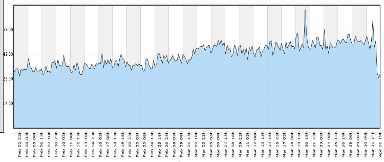
So what evidence do I have that it can make a difference ? I now try and log CPU and hard disk temperatures for any machine I manage to my central Pandora FMS system. Microsoft Windows is very poor in exposing the CPU temperature sensors with no proper support at all via WMI so you must rely on 3rd party programs of which few have a command line interface to allow cron-like collection and central logging. GNU/Linux machines on the other hand have the lm-sensors package and that generally works for all modern machines and gives a command-line access to the CPU temperatures (use the hddtemp package for hard disks). Here is a graph of a Ubuntu 11.04 based server we have in a kitchen environment,

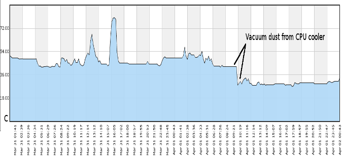
About 3 months ago the average CPU temperature was about 30 degrees C (86 F) but this has trended up and was now about 44 degrees C (111 F) when idle. So for a spring-clean I decided to open the case and clean it out. There wasn’t a massive amount of dust but the AMD stock cooler vanes were clogged. Just used a vacuum cleaner to suck up the dust. Hold the CPU cooler fan to stop it from manically spinning around and just put the vacuum cleaner on maximum and pass over the cooler fan. The dust should slowly suck out.

As you can see it made a dramatic change to the CPU temp with a 14 degree C drop  (about 25 F drop). This is now the 3rd retail-domestic machine that I have cleaned and observed the side-effects and it is certainly worthwhile as long as you have recorded the CPU temperature over time to give yourself (and the client) the objective evidence that this is a necessary job.

Foil-backed insulation blocking WIFI

Client has fixed up an old building and has used solid insulation which has an aluminium foil backing that acts as a heat and vapour block. It also stops WIFI dead.

Normally this wouldn’t be a problem and all your signals would be under the roof but this client has a 3-story rustic building with the office at the top and a bedroom at the back on the ground floor with a new roof. Whilst the WIFI signals are fine from the top to the bottom of the main building, immediately you pass under the foil-insulation of the extension then the signals stop.

The most cost effective solution to get WIFI to this back room without running Ethernet cables through meter thick stone walls is to use powerline adapters. Recently I have seen the retail prices for these plummet to less than 50 Euros per pair (for TP-Link brand from Amazon.it or Amazon.co.uk). Currently testing these out and they are looking fine but there is one caution that you need to consider.

These units give off a high frequency audible noise. It is like the flyback transformer of an old style CRT or TV. From experience with different customers these high frequencies can be annoying and frustrating to remove. So you may need to use powerline technology to sneak through the building and then for the last few meters use a cheap switch plus long pre-made ethernet cables or another WIFI AP.

Microwave oven wiring fix for scooter wiring

The wire on the temperature gauge of my Aprilia Leonardo finally broke near the socket so the temperature reading stayed on low/no reading. If you look you can see a metal pin on the gauge that the needle sits against. After about 2 minutes of motor operation the needle should move off that pin. If it doesn’t then check that wire.

To do this ideally remove the right-hand side inspection panel and the temperature sensor is towards the middle bolted into the engine block around the same level as the starter motor (the oil pressure sensor is much lower).

This can both come loose (mine did a year before) or finally snap off at the plug. The temperature sensor has a spade plug end on it so nothing special but you don’t have any slack to play with on the wiring loom so you need an extension wire but I discovered a nice fix that will probably work for you too.

Many months ago I had picked up a junk microwave from the road side: I had pulled it apart to see what was inside and I remember keeping all the wiring looms from the microwave. The wiring loom connects all the microwave door interlock switches together to the control board. Looking around for suitable wire to repair the bike I noticed that the microwave loom had these nice sockets with moulded plastic covers and reasonably good sized cable. The cable lengths are only a short distance of a few inches/centimetres but that’s all I needed.

I tried one of the sockets fitted the temperature sensor on the bike and it clicked on perfectly. So I chopped off one of the sockets with about 3 inches/8 cm of wire on it, stripped back the end and then stripped back the end of the broken wire on the bike, cleaned the corrosion away and then used a barrel/coupler connector to join the new bit of ex-microwave wire to the bike wiring loom wire.

It worked.

Pop stuck-on Pentium4 from heatsinks using Salmon slicing knife

Client PC had some weird problems; could start sometimes, would shutdown, runs “slow” though usually fine. Used CPUID HWMonitor and the SiSoftware sandra to see what’s up and the CPU temperature was high (75 Deg C).

The SiSoftware sandra processor reports a CPU temperature which correlates with the HWMonitor TMPIN1.

Got this desktop back to base and popped the hood. Cleaned out the usual dust bunnies and then decided to check the CPU seating on the heatsink. This is a socket 478 on an ASRock motherboard so levered the heatsink retaining clip but the heatsink wouldn’t come out and seemed frozen in place. Used a bit of force and when I did get it out the CPU had been pulled out too from its ZIF – the CPU was firmly glued to the heatsink by dry white heatsink compound.

I thought of what to get that off – a scalpel would be too sharp and dangerous and not big enough and then I remembered my favourite kitchen knife – the slicing/ham/salmon knife. This is 30 cm long, straight edged (not serrated), thin, about 2cm wide and a rounded tip.

I put the knife edge up to where one edge of the CPU and heatsink touched and then applied pressure. The knife broke the glue bond and the CPU was loose. Used the knife to scrape the heatsink clean.

Re-assembly was easy, re-inserted the CPU back into its ZIF socket that it had been pulled from (obviously open the locking lever first !), added usual thin smear of new thermal grease to the heatsink and put it back though you may have to do this in conjunction with the heatsink retaining clips as the heatsink may need to go in at an angle so the clips can hook into the bracket.

Screwed back in fans and powered up. BIOS looked good with a starting reading from cold of 28 deg C then working its way up to 34 deg C. Then ran Windows and now HWMonitor and SiSoftware sandra say 38 deg C and this maxes out to 42 deg C.

That’s up to a 30 degree C drop. Now the system should stay stable.

ps: As a safety note clean the knife of any residue. White greases are ceramic based and one important ceramic is Beryllium oxide which is poisonous in a loose form. These are not used for thermal grease now but may have been used in the past and unless you installed the heatsink yourself (in this case I didn’t) you won’t know what the risk is.

A fix for Korg nanoPAD PADs not working

I’d bought this over a year ago and never really got it working and put it aside as I had got a nanoKEY and a nanoPAD (Black) and just used the nanoKEY.

Recently I found this again in the cupboard and thought that I really had to get to the bottom of why it did not go (I was using Ubuntu so blamed that to start with without following it up).

I plugged it into my Ubuntu machine (10.10) and used the MIDI monitor in Qmidiroute and only saw the X-Y events – this does pitch modulation, plus the system events for the scene button but not a single event from the 12 PADs.

I also plugged it into Windows and used a MIDI monitor and also had no MIDI events for the PADs. This really did seem to be a hardware problem and nothing to do with Ubuntu. I really should have done this test before the warranty expired but this meant I could open it up without any guilt.

Under the bottom of the case under the tiny rubber feet are 6 screws. Remove these. You will see a metal plate which is the support for the 12 PADs plus a copper shield, 1 large flexible ribbon cable for the PADs and underneath that 1 small flexible ribbon cable for the X-Y control. These plug into a PCB.

With it plugged into the USB and with the MIDI monitor program going I checked I had X-Y events and no PAD events. I then popped off the clip to the large cable that goes to the PADs and as I removed it then I got events. This suggested some alignment issue or short i.e. the chip is OK.

I unscrewed the PADs metal plate – I removed the copper shield cable (it is glued at the PAD plate end) and had a look. Nothing really to see. It has the 12 square sections that are the sensor elements on plastic film and a big rubber molding for the PAD buttons. No obvious damage.

I then did something weird but I wanted to see how the pads sensor elements were constructed as it looked just like the internals of a some kinds of PC keyboards (they have a similar looking plastic film and flexible PCB though the nanoPAD uses Force Sensing Resistors); I peeled back the top layer of plastic that was over the first two buttons – JUST the first two buttons and peeled it back so that I didn’t crease the plastic. It has a lot of glue holding it down at the start and I wondered if this could be some issue but it peeled back OK (bit of force needed) and exposed the first two PAD elements (i.e.  the ones closest to the X-Y controller).

I then smoothed the plastic film back into place and plugged the PAD cable back into the PCB.

I tried it and it worked !

It is velocity sensitive and I correctly got events on all PADs with a very light touch yielding say a velocity value of 25 and a bash yielding a velocity of the maximum of 127. I hit them very hard with fingers and very light and they all seemed to be the same sensitivity.

I re-assembled; PAD metal frame screwed back, pushed back copper shield onto PAD metal frame, screwed case back on and added rubber feet into place.

Still worked. I was very pleased.

I could not see what the heck was actually really wrong in the end though I had cleared the fault. Maybe that glue was holding in moisture from manufacture ? Who knows as the problem is now gone and it doesn’t seem to be coming back for my unit yet.

I’d looked around for fixes to the Korg nanoPAD and I saw a number of people with the PADs failing even after light (or in my case practically no)  use. So I suspect a manufacturing defect and as far as I can see Korg seem happy to replace the units if you report this in warranty period so there are no real tears here except loss of your time.

It could be that the fix I described above i.e. peeling back that top layer of the plastic film on the start of the PAD sensor assembly works for you too and there is no harm in trying this if you have a broken unit out of warranty.