Toshiba Satellite R630 power button replace.

This is reasonably easy but you will have to take off the whole underside/back/bottom plate of the laptop. A client managed to break the power button on their Toshiba R630-141 laptop. The button is a single plastic part that consists of the button, a plastic spring leaf and a complex base.

With the screen shut, and upside down, remove the battery (and the power and any other cables if still plugged in). On the underside (base) , unscrew all the screws. There are two main sizes of screws but the short ones have a tiny “F4” printed near them on the case so not too much of an issue if they are mixed up with the longer screws. Remove the 3 cover plates (hard disk, memory and an unused docking port). The back cannot come off until one of the screws under the hard disk cover plate is also removed (it is obscured by the cover plate). Remove the hard disk by lifting the disk up and unplugging its SATA socket. This is attached to a ribbon cable and it has a plastic backed cushion. I did the hard disk removal too but I don’t think it is really necessary. If you do not remove the hard disk then note that the hard disk has no other clamp so be careful it doesn’t fall out and dangle from its ribbon cable when you are looking at the power switch from the front panel.

The whole base should now be removable but you will have to lift the DVD side first to then clear the sockets from the plastic holes on the USB port side. If it isn’t lifting then you may have forgotten a screw. You should now have the back removed and will see the hinges. The power switch is near the power socket. You will have to…

  1. remove the screw that holds that hinge down,
  2. lift up the hinge (it is very stiff but you can do this by your fingers) to clear the plastic cable guide,
  3. ease out the cables (twin, grey and black) and remove the plastic cable guide,
  4. remove the power socket (its cable unclips and it slides up)
  5. unscrew one silver screw that is closest to the power socket on the CPU board and another that is diametrically opposite on this board (these two screws loosen the power/CPU board).

This will allow the CPU board power socket edge near the radiator grills to be lifted up enough (at least 1 cm) to remove and replace the power switch plastic parts that are hidden underneath it.  The power switch button is not screwed in but the plastic casting has guide holes and a plastic spring clip. It is fed down, with the guide pin keeping it in alignment, and then the plastic spring clip clips into the front cover plastic with a firm click. You should see that the button is correctly in its hole (which is what you push from the front).  You can carefully open the front cover to see that the power switch is correctly seated.

Reassemble in reverse order,

  1. Blow out any dust on the base cover. It will have significant dust on the grill
  2. add the CPU board screws (2x)
  3. add the Power cable and socket
  4. add the Cable guide, feeding the twin cable into guide
  5. Push back the Hinge onto the cable guide (it will be stiff) and screw to clamp down cable guide
  6. Refit the hard disk and its plastic backed cushion if you had removed this.
  7. Refit base, click in the USB socket side first. Check no gaps or pinched cables
  8. Re-Install all screws, remember F4 screw holes are the short screws
  9. Reinstall all cover plates

The laptop is now repaired. Reinstall the battery, and power up. Keep an eye on things you may have disturbed such as, CPU cooling, memory sizes, WIFI signal strength, DVD operation, audio jack.

The power button replace should take just over one hour.

yarn install fails as it is using cmdtest package and not yarn

yarn was previously provided by cmttest and these are very different programs to yarn the package manager.  If you are using software sources (e.g. FarmBot.io)  that are managed through yarn (you will find a yarn.lock file with the software source) but when you try and run yarn install and then you get e.g.

yarn install
ERROR: [Errno 2] No such file or directory: 'install'

then firstly check to make sure that cmdtest is not installed.

sudo apt remove cmdtest

You would install yarn with

sudo apt-get install yarn

See the yarn packager web site for more details on installation.

ASUS X51R laptop CMOS battery bad causes blank screen no boot

The ASUS X51R laptop exhibits a strange failure when its built-in CMOS battery is dead or low. Rather than having some kind of fall-back it basically ceases to operate from power-on. In some cases it will post a message about CMOS battery low but when you continue then it stays on a blank screen and doesn’t boot. Most of the time it will just power to a blank screen i.e. the laptop seems to startup and have fans and disk startup but no further POST or booting into the operating system. The “Zz” light may be on all the time but that is not relevant.

A client got this problem – one day it was booting fine and the next it was a blank screen so there is no early warning of impending failure.

The CMOS battery is a 3 Volt CR2032 style battery. These last for around 7 years so always keep them in their packaging so you can see the expiration date. Ideally use a new battery from a trustworthy supplier for a client laptop as it takes a long time to replace.

To change the CMOS battery you need to do a complete tear down of the laptop to the motherboard. There is nothing unusual with this teardown – if you have never stripped a laptop then this is not a job for you. I have done a lot so this was pretty trivial tear down,

– remove main battery, memory, hard disk, and WIFI
– remove all visible screws on bottom and back (they are all different sizes so draw a picture and keep them in separate piles),
– push in the 3-tabs at top edge of keyboard and lever out keyboard (unclip ribbon cable),
– lay screen fully back and lever up plastic covers on screen hinges and the curved plastic cover that is in the middle that is over the screen cables to motherboard plugs
– unclip the screen cables from the motherboard and flip over and unclip the WIFI cables and poke the wires out as you remove the screen (the screen itself just stays assembled to its hinges with 2x WIFI cables and 2x multi-way screen cables attached)
– unscrew the screws that you can see that were being hid by the keyboard and that were hidden by the screen that hold the top cover down
– unclip the narrow touchpad ribbon cable and pop up the top cover,
– unscrew the screws on the motherboard – there is a arrow-head symbol near each hole that marks which holes are used but ideally draw a picture and keep the screws seperate,
– unclip the fan assembly and cable, the speaker cable (towards middle front of motherboard) and battery feed ribbon cable and remove the DVD/CD drive if it’s not yet removed (it should slide out as its retaining screw is removed),
– carefully lift out the motherboard,
– you will see the battery on the bottom – it is a standard fitting – use a screwdriver to pop in the retaining tab and then remove and dispose – remember which way it was oriented but the +ve case side should be up (-ve small disk side down),
– do not use your fingers to touch your new battery but remove it from its packaging and clean your new battery with a clean dry cloth and then insert into the socket without touching it with bare hands. The reason to not touch it is that your hands have oil on them and over many years this can corrode.
– Re-assemble in reverse order.

Before re-assembling fan then please clean out the dust. There is nothing special to remember on re-assembly.

When assembled then it will boot instantly without any problems. The date and time will be wrong (reset to 2007 or similar) but you can easily reset this. With a new CMOS battery the laptop should last for another 5-7 years. The whole job takes about 1.5 hours.

Opera slow Flash due to multiple plugin locations enabled

I use Opera as one of a number of browsers for testing purposes. Noticed that Flash was jumpy (Opera 12.16 with flash 11.2 r202 on Ubuntu 14.04 64 bit). It took a while to find the problem but I believe that it was due to multiple flash plugins enabled. To see what plugins are enabled go to,

Opera -> Page -> Developer Tools -> Plug-ins

(or the shortcut URL of opera:plugins )

If you see multiple locations of the Shockwave flash enabled then disable all except one e.g. leave the one located at,  /usr/lib/mozilla/plugins/libflashplayer.so enabled.

Restart Opera and hopefully this may clear your problem.

PS3 Bluray drive clean-out dust bunnies and no disk load

This is electronic related so I’m going to post this. Three different problems,

  • Right at the start of the summer holidays our children’s PS3 bluray disk drive started to play up; symptoms are spurious ejects after load and poor reading of disks.
  • Then at the Christmas holidays the disks were not loading at all and the blue load light was always on.
  • and there has also always been a problem of poor on/off switch performance.

What I did (out of warranty repair – if your PS3 is still under warranty then let the store work out the problem),

1) Slide-remove the decorative cover (to left when PS3 is lying down flat with the bluray slot to the right) and then undo the 7 screws on the top case cover (has one short size screw and the rest are long – the hole with an ‘S’ is the short screw). Push in the tab at the back right hand side and then lift off the case cover up from the back – there are a row of tabs on the front that you pivot it out of these.
2) Unscrew the PSU – it has 5 screws in total (2 longer plus 3 medium), one plug on the front, the main 230 Volts on the back AND it has a pair of blade pins hidden towards the front so just lift it UP to slide out of the socket.
3) Un-connect the Bluray DVD ribbon cable by flipping up the black locking tab and remove the white 4-wire power plug for the Bluray on the front.
4) Flip the Bluray over and remove the 2 x silver and 2 x black tiny screws.
5) Remove the metal case cover. The DVD top retainer will fall out. It is OK it’s held in by nothing but the case.
6) Note the EXACT position of the white rotary parts that you can see. Remove the two tiny black screws on the main part of the disk loader mechanism – they are towards front. Pop up the two tabs on each side carefully. This whole lot comes off.
7) Pop in the tab in the middle of the front disk loader mechanism to release this. This lifts up.
8) Clean out all the dust bunnies. Note that the lefthand rack does not touch the black cog – that’s how it is designed.
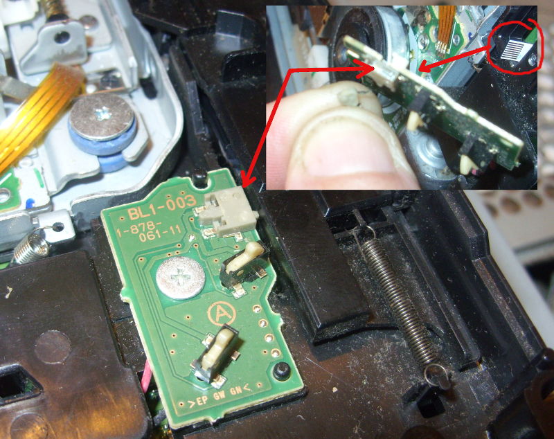
9) If disks are not loading or the blue disk load light remains on even when there is no disk in place then the right hand side has a PCB that has 3 tiny switches on it – 2 vertical that detect when disks are inserted and 1 flat that detects when the mechanism is in a ready position. Use a multimeter and check that these switches close circuit when pushed in and keep closed when you wiggle things around. The one I had fail was the flat one that gets moved by the tray mechanism. It can be dismantled and cleaned out (to do this unscrew the PCB, remove the flat ribbon on the underside, and use a finger-nail and pliers to pop out the switch lever. Clean any gunge on the back inside of the switch with a 0.5 mm solid wire e.g. wire gauge. ps3-load-sensor
10) Reassemble is in reverse BUT how the loader mechanism works is that as the disk is powered (tiny sensor switch to right) in then the left hand levers on the back part of the disk loader mechanism rotate anticlockwise as a disk is loaded and then this moves the left hand rack slider a bit so it hits the black cog. This cog then pulls the rack to the front and the slider then raises the platen. If you do not set the rotary parts right into the left hand slider then when the disk is loading it doesn’t rotate these bits of plastic so they don’t shift the slider to engage with the cog of the motor. You should be able to rotate the smaller left hand rotary part around so that it engages into a slot on the left hand slider – if you simulate a disk load then you will see it take up the slack in the left hand slider and hit the cog. If its doing that then this should work. It took a bit of practice to get this right.

Reassemble all the screws and stuff in reverse. There is no safety interlock so if you can run the Bluray with no cover and you should ideally do this without screen or controllers to verify the mechanism is loading and ejecting disks.  It will save you some hassle of re-assembling the lot only to have the disk disks not load !

If you are failing to get the disk to load right then you can run everything without covers or screws – just remember to keep the round white disk weight in place and DO NOT LOOK AT THE PRETTY LASER. If the PS3 starts up and the disk isn’t pulling in disks then check the ribbon cable is inserted right under the PSU. The LASER works but the motor won’t pull in disks if that ribbon cable under the PSU is out or out of alignment.

EXTRA: With the top cover off then the eject and power On/Off switch works by touching the small square metal pins on the PS3. These are connected to the outside case by metal strips that make contact when the case is re-assembled. To fix any poor On/Off switch (or eject switch) operation carefully lift up these metal pins so that they make better contact with the top case metal tabs.

That’s all – hopefully you’ll save the 40 quid for a new Bluray drive if you manage to get your old one cleaned out OK and your Playstation 3 will last for many years more.

vTiger 5.4.0 enable backup quirk

Note that from vTiger 6.0 onwards i.e. 6.5 and 7+ there is no default backup module. You’ll either have to buy a commercial module or roll your own script. The guide below will be obsolete.

I use the vTiger CRM product and it has a unusual quirk with enabling backups. Whilst the user interface (CRM settings -> Backup server) has check boxes to enable local and FTP backup the script actually tries to alter the following file, /user_privileges/enable_backup.php and in that set the two flags to a value of either true or false,

$enable_local_backup = 'true';

$enable_ftp_backup = 'false';

As the script has no permissions to do that then it gets a fopen() permission error (Warning: fopen(/*****/user_privileges/enable_backup.php): failed to open stream: Permission denied in /****/modules/Settings/SaveEnableBackup.php on line 43) and so when the ajax refreshes the screen it looks as if nothing has been done.

Without messing with your directory permissions then you can edit the /user_privileges/enable_backup.php manually.

Even if you manage to get the directory details into the local backup it will not work unless that enable local backup flag is set to true. It will say that it has done a backup but it will not save any file.

Fault finding CDI ignition Aprilia Leonardo

A week back we had a very violent thunderstorm. It blew up a laptop PSU (fuse blown) but the oddest one is that my scooter got blown over and when I tried to start it wouldn’t fire. Thought it was low fuel but after top-up of the tank and a lot of cranking it was pretty clear I had more of a problem. The rest of this post details how I fault-found this problem.

The ignition system for this generation of bikes is fairly simple consisting of a TDC sensor in and an output to the ignition coil primary (plus 12 V and ground).

When the ignition  key is turned on then this provides 12 V to the CDI and to one leg of the ignition  coil primary. The other leg of the ignition coil primary goes back to the CDI unit. To fire the coil the CDI unit applies and removes ground to this primary coil leg. So a high current pulse then flows through the primary which energizes the primary coil, which is then multiplied in voltage by the ratio of windings to the secondary coil, the pulse of electricity is then discharged through the ignition  leads through the spark plug to the engine ground. The CDI knows when to fire because a coil pickup on the flywheel tells it when it is TDC.

Checks – Ignition Coil and Sparkplug

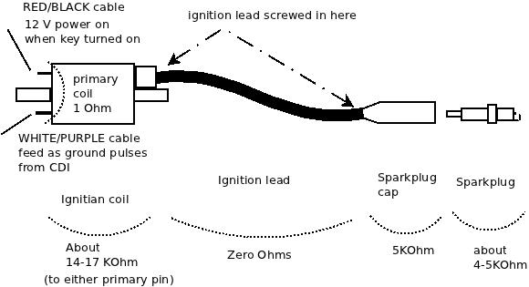
The ignition primary coil is easily checked. Looking at the coil (on the right hand side of the bike under the inspection panel), it has a RED/BLACK cable to the key, a WHITE/PURPLE cable to the CDI, a fat black cable to the sparkplug.

To stabilize the very high voltage secondary coil pulse  the sparkplug cap and the sparkplug are resistive. The cap is 5 KOhms and the sparkplug is also about 4-5 KOhms. The ignition lead is screwed into both the  ignition coil and the sparkplug cap. The coil and plug has what looks like a woodscrew poking out deep inside hidden in the coil or plug and you screw the ignition lead onto that point. The ignition lead cable can and will on older bikes have internal damage in its conductors near where the lead screws in if the cable is old. If you remove the sparkplug from the engine then click it back into the sparkplug cap then you should see about 25 KOhms from the centre electrode in the tip of the sparkplug back through to the primary coil (the primary and secondary are joined on one leg and it is only 1 ohm between the primary coil). If you do not then check the spark plug has about 4-5 KOhm resistance from its centre electrode in the tip to the small threaded end. If it doesn’t e.g. it is open circuit then replace that sparkplug and hopefully that is your only problem.

If it is OK then unscrew the ignition lead from the ignition coil secondary. Now measure the ignition coil secondary from the screw tip that you can see poking out to the primary coil tabs. If this is not about 17 KOhm but open circuit then you have a broken ignition coil but if it is a few KOhms then check the part is the same – secondary on ignition coils can be different. You really only care about shorts i.e. zero Ohms or open circuit i.e. infinite KOhms. Replace this if it is clearly broken.

If this is OK then measure from the ignition lead core wires (which you can now see on the end you unscrewed from the ignition coil) to the sparkplug cap.  It should be about 5 KOhm. If not then unscrew the sparkplug cap from the ignition cable. It has a similar woodscrew deep inside it that you screw the ignition lead onto. The cable is a multi-core of fine wire and it may have frayed and broken internally. Measure its resistance and it should be zero ohms. Wiggle the cable –  internal breaks can be felt as a soft section that more easily moves than the rest of the cable. If the cable is OK then measure the sparkplug cap and it should be 5KOhm. If it is not then replace this. If that is OK then you are disturbing the break that you originally detected and it is probably in the cable where it screws in to the coil or sparkplug cap. You may have enough spare lead to cut off the end to get to unfrayed core wires, if not then you need some new ignition cable.

Checks – CDI

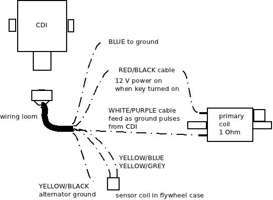
In my case I did all that but it wouldn’t fire.  Now you will have to remove the bike body covering to get at the CDI. I won’t describe that but you basically remove any helmet carrier on the rear, remove the read handhold, unscrew the rear light cluster, license plate holder, undo all the little screws under the seat, the big screws towards the lower front near the feet-stands and then slide the body panel back as one big mass. The CDI is on the right hand side with a 6-pin cable plug.

Unclip this and do the following checks by poking your multimeter probes into the socket,

  • BLUE is Earth – make sure it is and is zero ohms to the YELLOW/BLACK
  • WHITE/PURPLE goes to the Ignition coil primary – check it is zero ohms to that coil and that when the RED/BLACK is removed from the coil primary, that there is no shorts to ground or the RED/BLACK socket (here)
  • RED/BLACK goes to the 12VDC keyed off the ignition same as the power to the coil – so should be zero ohms to the battery positive.
  • YELLOW/GRAY goes to one side of the TDC sensor coil – there should be about 240 Ohms resistance between this pin to the YELLOW/BLUE
  • YELLOW//BLUE goes to the other side of the TDC sensor coil – see the YELLOW/GRAY cable.
  • YELLOW/BLACK is Earth so should be zero ohms to the engine frame.

If all those seem to be right then you are pretty well  left with one conclusion and that is the CDI itself is not working. This is fully sealed and cannot be repaired. Your best bet is to buy one second hand. Make sure you get the exact DENSO part number.

In my case the faulty unit had the WHITE/PURPLE signal which goes to the ignition  coil primary was always on as a ground signal. It should never be always on but pulse a ground. I can only guess it was shorted out inside the CDI. All that happened was that the ignition  coil would heat up.

Checks – firing sparkplug out of engine (caution)

This is a more dangerous check but I’ll include it for completeness. You can see if the sparkplug is sparking as follows,

  • remove sparkplug from engine and click back into the sparkplug plug. Feed the ignition lead and sparkplug to the right-hand side of the bike away from the open engine sparkplug hole and so you can see the spark when you fire ignition switch
  • Ideally fit a spare sparkplug into the engine sparkplug hole BUT if you do not then you must do this testing outside because petrol mist will leave the engine so you want a lot of ventilation
  • use a jumperlead to connect the sparkplug screw thread to the engine body. I use a battery jumper lead as these are very low resistance.
  • turn on the ignition and try to crank engine. You should see a bright blue-white spark pulses even in daylight. If you do then your starting problem is not ignition but perhaps fuel. If you get only ONE spark when the ignition is turned on then you have my problem of a shorted out CDI. If you get NO sparks then assuming your test setup is fine and you have tested all the other components then it is the CDI with a faulty open circuit.

Enjoy your bike riding !

Always getting number unavailable with Cisco dial plan

Dial plans are fairly easy to read but there is one little gotcha if you enter in one of these incorrectly: you will always get number unavailable.

You need to make sure that the dial plan you have entered in is valid i.e. it uses the | pipebar for delimiters and has no spurious close brackets ‘)’

The web interlace of a Cisco IP phone does not validate your input.

PHP Warning: Invalid argument supplied for foreach()

If you get a Warning: Invalid argument supplied for foreach() but the code looks and seems to work fine then the issue is that foreach() needs an array but you are passing a Boolean due to an error in a previous function.

You will see this problem where you have something that is returning an array or false e.g. glob() and then you pass the returned value to the foreach() without checking if the variable isn’t false. e.g. in this case glob() can return false if it can’t see the path,

        foreach( $paths as $path ) {
            $filenames = glob( $path['path'] );
            if ( $filenames != false ) {
                foreach( $filenames as $filename )

In that example if glob() failed on one of the paths then it would return false. In my example above I check that $filenames is not false before I use it with foreach(). You can also use is_array() as well. To confirm your theory on your code you can add in var_dump() before the foreach() on the variable that you pass to confirm the type of the variable of what you use in foreach().


Using error_log() with print_r() to gracefully debug PHP

When debugging php code (especially Open Source code you have not written yourself) then to get a feeling of what is passed around when it doesn’t work I find that the print_r() function is very useful.

Trouble is that if you just throw in print_r() into the code where you think it is faulty then you can upset json, AJAX or your web page layouts as the print_r() splatters stuff to your displayed web page or in some cases the PHP file is not going to a browser (e.g. the PayPal IPN notify).

The trick is to throw it at the error log as follows e.g. if I was tracing what $number was being set to then I would use….

error_log(print_r($number,true));

note that you MUST set that print_r() option to “true” so that it returns a string. This string is then sent to the error_log() function which formats it with referrer details and puts it into the Apache error log.

Where does it end up ? Well on my test system on a non-vHost it is /var/log/apache2/error.log and on a vHosted server it is :/var/www/vhosts/<domain name>/statistics/logs/error_log so on your own system it will be a similar Apache error log file. Just tail that file to see what the messages are which will be something like this (in this example the $number was “2008” so the output for that error log message was,

[Sun Jan 01 13:21:12 2012] [error] [client 192.168.2.2] 2008, referer: http://19
2.168.2.250/bluebox/index.php/numbermanager/index

To synchronize the log messages with your testing then just look at the logging time.

Ring then disconnect on registered VOIP SIP trunks

The setup is a (VOIP) SIP trunk provider in the UK connecting via the internet to a FreeSWITCH PBX with the Blue.box web interface that is attached to the Internet via a NAT routed ADSL last mile. The local IP telephones connect to the FreeSWITCH PBX and the different trunks from the UK (using 3 trunks for 3 different projects) should appear on one of three of the 5 extension lines on a Cisco SPA 525G.

The trunk to the UK was registered correctly as far as FreeSWITCH/Blue.box was concerned but when you called the UK phone number from the PSTN then it rang but then went to disconnect tone. What was expected was that the call would use the SIP trunk to connect via the FreeSWITCH to the IP phone on the client site and light up the correct extension.

The problem is that in Blue.box I had configured the trunk Bind to the Authenticated SIP interface and not the Authenticated SIP NAT interface. Changed it to the Authenticated SIP NAT interface and that worked. The Authenticated SIP NAT port has port 5070, auto-detect IP address via UPnP whereas the Authenticate SIP port I have is on the fixed local LAN private IP address used for local IP phones to proxy register against. These SIP interfaces are defined in blue.box under Connectivity -> SIP Interface and the trunk is defined under Connectivity -> Trunk manager.

You will see the FreeSWITCH console log has,

2011-12-25 12:29:06.274781 [WARNING] sofia_reg.c:1445
SIP auth challenge (INVITE) on sofia profile 'sipinterface_4'
for [44XXXXXXXX@sipprovider.example.com] from ip X.Y.Z.A

for each inbound call attempt. Bit of a first day of setup gotcha.


No text-to-speech with Flite on Freeswitch/Blue.box IVR

If you have configured a feature code that uses text-to-speech e.g. a talking clock or if you are setting up an auto attendant (IVR) on a new Freeswitch+Blue.box system and you have selected the flite voice but when you connect to the auto attendant Assigned Number you get no message audio even though you have selected the Flite voice then you can test this problem very quickly.

Look at the freeswitch console log and you should see a error message,

2012-12-26 09:57:14.381330 [ERR] switch_core_speech.c:61 Invalid speech module [flite]!
2012-12-26 09:57:14.381330 [ERR] switch_ivr_play_say.c:2439 Invalid TTS module!

If you are not at the console and if you are testing an IVR then connect to the IVR from a phone and  hit one of the key mapping option numbers that you have configured for it to action and if this works (which they probably will) then your problem is that you have not enabled the mod_flite in Freeswitch source modules.conf or the module is not automatically loading.

This is easy to fix. Edit the /usr/local/src/freeswitch/modules.conf  and uncomment the line,

asr_tts/mod_flite

(also make sure that you have mod_cepstral commented out as you can’t use flite and cepstral at the same time. Cepstral is licensed, albeit not very expensive – about 30 dollars per voice – and you can test with their TTS voices though the TTS engine will periodically insert nag messages.)

Now do a make on Freeswitch. This will see that you have enabled the mod_flite and it will download the flite package from http://files.freeswitch.org/downloads/libs  (about 14 Megabytes).

Note that if you break the download then you must cd to /usr/local/src/freeswitch/libs and sudo rm -R flite-1.5.1-current*  or similar to clean up the broken download and then run make again.

After the make then do a make install.

Once that has done (or perhaps you had already had that uncommented) then you must make sure that the module is autoloaded. To check this go to the runtime program path which is usually /usr/local/freeswitch) e.g.

cd /usr/local/freeswitch/conf/autoload_configs

and edit the  modules.conf.xml and again uncomment the mod_flite line so it is  the only one uncommented,

  <!-- ASR /TTS -->
    <load module="mod_flite"/> <!-- -->
    <!-- <load module="mod_pocketsphinx"/> -->
    <!-- <load module="mod_cepstral"/> -->
    <!-- <load module="mod_tts_commandline"/> -->
    <!-- <load module="mod_rss"/> -->

now restart freeswitch. Your feature code text to speech will now work.

Truthfully though the Flite TTS is synthetic (e.g. the rms voice) and will never be as good as a human spoken voice but it does allow you to quickly setup what option codes to use and test your options before you get a human speaker to say a script.

If you are getting someone to say the script (or yourself !) in-house and want a low-cost recording solution without a professional sound recording setup then I use Audacity with an ordinary microphone (VOIP headset) and a sheet of copy paper as a de-popper. See my post here for details.

Using strace to identify Plesk 10 blank screen problems

Plesk 10 uses its own web server which runs as a process called sw-cp-serverd. This is started by init with a command line that results in the processing being called,

/usr/sbin/sw-cp-serverd -f /etc/sw-cp-server/config

That config directory is where you will find which ports it binds to and the URL re-writes. You should not change the bound port as that can upset other applications.
If you connect to Plesk on port 8443 and you get a blank screen or if you can logon to Plesk and administrative functions are blank then this is due to some problem with that server or the files that it is accessing.

To see what system calls it is doing and so help identify where to look next you can use strace as follows,

sudo strace  -p `ps -C sw-cp-serverd -o pid=` -s 8443 -o mydebugfile.txt

(note using backtics to run the ps command – if you are having trouble finding the backtic on your keyboard then you can do a ps and grep for that process name and then put the process number into that place in the strace command). If strace is not installed on your system (usually isn’t) then you can install it using your usual package manager or if using Ubuntu then I used,

sudo apt-get install strace

Don’t worry about EAGAIN (Resource temporarily unavailable) messages – this is just how it displays for non-blocking I/O when there is no data to read.

The really interesting ones are the connect(socket #..) then the writev(socket #..) and then read(socket #,..), where the socket # is the same socket number that was setup and in the writev() you can see your request with all the browser details and the read() that follows gives the response.

If the read() has a Status: 500 Internal Server Error in it then this won’t come back to your browser screen – which will stay blank.

If this happens then you have an inconsistent Plesk installation and this requires support from someone who knows how the Plesk server works.


Enabling IPv6 in Ubuntu ufw

I was creating a new web site dogstarplanet.com and as I was installing it on my IPv6 enabled host I thought I would setup the A and AAAA records for the same CNAME.

Windows based PCs without any IPv6 routing obviously ignore any AAAA records and the browser connects to the site as expected but an Ubuntu desktop I was using was unable to get to the site – both Firefox and Opera not connecting.

I loaded Wireshark to see if my traffic was leaving and though I could see the DNS queries for AAAA and A records there was no TSP traffic (Tunnel Setup Protocol) to the freenet6.net IPv4 address  (I’m using gogoc package out of the box). This means that the browser connection was not getting to the tunnel interface. This means firewalling or kernel.

If I run the Firestarter then I also see the tun (routed IP tunnel) but no traffic passes (note: that I have since removed Firestarter and now run Gufw).

Well the IPv6 is in the kernel but I had ufw enabled and that doesn’t have IPv6 enabled by default so you get the error message if you try and use ping6 of e.g.

ping6 ipv6.google.com
 ping: sendmsg: Operation not permitted
 ping: sendmsg: Operation not permitted
 ping: sendmsg: Operation not permitted
 ...

If it is safe you can quickly test this is your problem by turning off the ufw with the command,

sudo ufw disable

Now your ping6 should work. If it does not then you have a tunnel problem. Use the command netstat  -rn6  to see if you have tun entries.

It is easy to enable IPv6 in ufw by editing /etc/default/ufw and towards the top there is a line of IPV6=no which you change to IPV6=yes

Save that and then disable and then enable the firewall i.e. sudo ufw enable or do a sudo ufw reload if it was still running.

Now you will be able to ping6 and connect to IPv6 enable hosts using a browser. Note that when you ping6 then there is a PTR query (that you would only see in wireshark) and you may get a no such name response if you have not configured your host DNS records right so if you are committed to setting up IPv6 on your host then please check you have added a suitable DNS PTR entry for the dotted nibble PTR part of your IPv6 address. Very few protocols, perhaps only mail connections and obviously ping6, use IPv6 PTR queries.

Pop stuck-on Pentium4 from heatsinks using Salmon slicing knife

Client PC had some weird problems; could start sometimes, would shutdown, runs “slow” though usually fine. Used CPUID HWMonitor and the SiSoftware sandra to see what’s up and the CPU temperature was high (75 Deg C).

The SiSoftware sandra processor reports a CPU temperature which correlates with the HWMonitor TMPIN1.

Got this desktop back to base and popped the hood. Cleaned out the usual dust bunnies and then decided to check the CPU seating on the heatsink. This is a socket 478 on an ASRock motherboard so levered the heatsink retaining clip but the heatsink wouldn’t come out and seemed frozen in place. Used a bit of force and when I did get it out the CPU had been pulled out too from its ZIF – the CPU was firmly glued to the heatsink by dry white heatsink compound.

I thought of what to get that off – a scalpel would be too sharp and dangerous and not big enough and then I remembered my favourite kitchen knife – the slicing/ham/salmon knife. This is 30 cm long, straight edged (not serrated), thin, about 2cm wide and a rounded tip.

I put the knife edge up to where one edge of the CPU and heatsink touched and then applied pressure. The knife broke the glue bond and the CPU was loose. Used the knife to scrape the heatsink clean.

Re-assembly was easy, re-inserted the CPU back into its ZIF socket that it had been pulled from (obviously open the locking lever first !), added usual thin smear of new thermal grease to the heatsink and put it back though you may have to do this in conjunction with the heatsink retaining clips as the heatsink may need to go in at an angle so the clips can hook into the bracket.

Screwed back in fans and powered up. BIOS looked good with a starting reading from cold of 28 deg C then working its way up to 34 deg C. Then ran Windows and now HWMonitor and SiSoftware sandra say 38 deg C and this maxes out to 42 deg C.

That’s up to a 30 degree C drop. Now the system should stay stable.

ps: As a safety note clean the knife of any residue. White greases are ceramic based and one important ceramic is Beryllium oxide which is poisonous in a loose form. These are not used for thermal grease now but may have been used in the past and unless you installed the heatsink yourself (in this case I didn’t) you won’t know what the risk is.