Changing Joomla! MySQL user password without outages.

Changing your Joomla! MySQL database password without a loss of service is done as follows,

1) Open  the existing configuration.php file for Joomla! (found in your web site root) and print or save the details. This gives you a backup copy.

2) Use your cpanel (generally cpanel but there may be other hosting backends to access the MySQL database users) and add a new database user with a suitably strong password. Take care here and observe the cpanel error messages. Unless the password is strong enough it won’t save the values.

3) Assign this new MySQL database user to your existing Joomla database with all privileges.  Thus it is running in parallel with the existing MySQL database user.

4) Now edit the configuration.php file for Joomla! (found in your web site root) and change the two entries,

$db =
$password =

to these new MySQL database user values and then save that file back to the server. Joomla! will now be using this new database user.

5) Then you must verify this is true by going into the administration for Joomla and looking under Site -> Global Configuration ->Server and seeing that the database settings username is the new username.

6) If so then use cpanel to delete the old MySQL username or at  the very least change the password to something new.

Why do it this way – why not just change the MySQL database password ?  Because of timing, you cannot change the MySQL database password and the configuration.php file instantaneously. By adding a new database user that is waiting to be used and then changing Joomla configuration there is no loss of service and you can easily verify that it is working on the new setting by checking the Joomla administration screens.

A third party ideally should not know your MySQL passwords or be able to access your MySQL databases remotely but on shared hosting where there is just one MySQL engine running then any account on that machine can access your databases if they knew the database and username and password details.

Enabling IPv6 in Ubuntu ufw

I was creating a new web site dogstarplanet.com and as I was installing it on my IPv6 enabled host I thought I would setup the A and AAAA records for the same CNAME.

Windows based PCs without any IPv6 routing obviously ignore any AAAA records and the browser connects to the site as expected but an Ubuntu desktop I was using was unable to get to the site – both Firefox and Opera not connecting.

I loaded Wireshark to see if my traffic was leaving and though I could see the DNS queries for AAAA and A records there was no TSP traffic (Tunnel Setup Protocol) to the freenet6.net IPv4 address  (I’m using gogoc package out of the box). This means that the browser connection was not getting to the tunnel interface. This means firewalling or kernel.

If I run the Firestarter then I also see the tun (routed IP tunnel) but no traffic passes (note: that I have since removed Firestarter and now run Gufw).

Well the IPv6 is in the kernel but I had ufw enabled and that doesn’t have IPv6 enabled by default so you get the error message if you try and use ping6 of e.g.

ping6 ipv6.google.com
 ping: sendmsg: Operation not permitted
 ping: sendmsg: Operation not permitted
 ping: sendmsg: Operation not permitted
 ...

If it is safe you can quickly test this is your problem by turning off the ufw with the command,

sudo ufw disable

Now your ping6 should work. If it does not then you have a tunnel problem. Use the command netstat  -rn6  to see if you have tun entries.

It is easy to enable IPv6 in ufw by editing /etc/default/ufw and towards the top there is a line of IPV6=no which you change to IPV6=yes

Save that and then disable and then enable the firewall i.e. sudo ufw enable or do a sudo ufw reload if it was still running.

Now you will be able to ping6 and connect to IPv6 enable hosts using a browser. Note that when you ping6 then there is a PTR query (that you would only see in wireshark) and you may get a no such name response if you have not configured your host DNS records right so if you are committed to setting up IPv6 on your host then please check you have added a suitable DNS PTR entry for the dotted nibble PTR part of your IPv6 address. Very few protocols, perhaps only mail connections and obviously ping6, use IPv6 PTR queries.

Adding WP 3.0 custom menus to older templates

For our LifeSignPress.com web site we have used a nice template by cssmayo.com called Creative by Nature.

Recently we wanted to add a link in the navigation menus so we opened up the Custom Menus for the site and then saw that it did not support the new WordPress 3.0 custom menus.

All is not lost – it is easy to add in the same functionality to this older template without doing many changes and with no CSS style changes.

Here is how I changed the Creative By Nature v0.1 template to use the WordPress 3.0 custom menus,

1) Open your site and select the menu in a browser and then right-mouse and view selection text. Print this out. This is to just get an idea on the div, ul, il, a and spans that are used.

The template we’re using had a div wrapper that was an id of “navigation” and then a ul and then all the a hrefs but the link text was in a span. Now this navigation ID and the span is important as you need to mimic this in the new WordPress 3.0 custom menu unless you plan on changing the CSS style sheet.

2) Firstly find where the navigation menu is located. It will probably be in your template in a file called header.php or a similar name and now find where the menu is generated. It will be a function that is echoed or something similar e.g. we had,

<div id="navigation">
 <ul> 
 <?php echo _generate_navigation(); ?> 
 </ul>
</div>

The “_generate_navigation” is in the theme’s functions.php file. The menu generation will be between these two files i.e. your theme layout code file and your theme functions code file.

3) Now comment or remove the old code that generated the navigation menu and add in your replacement as below, setting the container_id to be the same as the div ID and if needed also wrapping the link text in a <span></span> by setting the link_before and link_after variables e.g.,

<?php wp_nav_menu(array('menu' => 'header_menu',
 'container_id' => 'navigation', 
 'link_before' => '<span>',
 'link_after' => '</span>' )); ?>

In our example that mimics the html that is generated for the same CSS to be used thus no need to change the CSS stylesheet for the theme. For the defaults for this wp_nav_menu() function see here – http://codex.wordpress.org/Function_Reference/wp_nav_menu

4) In the functions.php file for this template you will have to add the following code,

add_action('init', 'register_custom_menu');

function register_custom_menu() {
register_nav_menu('header_menu', __('Header Menu'));
}

You can add as many menus as you like though you would use register_nav_menus() e.g.

...
register_nav_menus( array( 'header_menu' => 'Header Menu', 
 'footer_menu' => 'Footer Menu'));
...

and you can edit out the old _generate_navigation() function if you want. Note that if you want to keep both < 3.0 navigation menus and 3.0 custom menu features at the same time then keep everything and in the header file or in the functions.php you could add a test e.g. if ( function_exists( ‘wp_nav_menu’ ) ) and then use the new 3.0 menus or else use the theme’s old code if that function_exists() returns false.

Pop stuck-on Pentium4 from heatsinks using Salmon slicing knife

Client PC had some weird problems; could start sometimes, would shutdown, runs “slow” though usually fine. Used CPUID HWMonitor and the SiSoftware sandra to see what’s up and the CPU temperature was high (75 Deg C).

The SiSoftware sandra processor reports a CPU temperature which correlates with the HWMonitor TMPIN1.

Got this desktop back to base and popped the hood. Cleaned out the usual dust bunnies and then decided to check the CPU seating on the heatsink. This is a socket 478 on an ASRock motherboard so levered the heatsink retaining clip but the heatsink wouldn’t come out and seemed frozen in place. Used a bit of force and when I did get it out the CPU had been pulled out too from its ZIF – the CPU was firmly glued to the heatsink by dry white heatsink compound.

I thought of what to get that off – a scalpel would be too sharp and dangerous and not big enough and then I remembered my favourite kitchen knife – the slicing/ham/salmon knife. This is 30 cm long, straight edged (not serrated), thin, about 2cm wide and a rounded tip.

I put the knife edge up to where one edge of the CPU and heatsink touched and then applied pressure. The knife broke the glue bond and the CPU was loose. Used the knife to scrape the heatsink clean.

Re-assembly was easy, re-inserted the CPU back into its ZIF socket that it had been pulled from (obviously open the locking lever first !), added usual thin smear of new thermal grease to the heatsink and put it back though you may have to do this in conjunction with the heatsink retaining clips as the heatsink may need to go in at an angle so the clips can hook into the bracket.

Screwed back in fans and powered up. BIOS looked good with a starting reading from cold of 28 deg C then working its way up to 34 deg C. Then ran Windows and now HWMonitor and SiSoftware sandra say 38 deg C and this maxes out to 42 deg C.

That’s up to a 30 degree C drop. Now the system should stay stable.

ps: As a safety note clean the knife of any residue. White greases are ceramic based and one important ceramic is Beryllium oxide which is poisonous in a loose form. These are not used for thermal grease now but may have been used in the past and unless you installed the heatsink yourself (in this case I didn’t) you won’t know what the risk is.

Address collision on range extended LAN after re-numbering main LAN

Client had decided to change ADSL provider. They got sent a new ADSL modem and I had to install this. The modem didn’t need any configuring as it was ready-to-go out of the box but its default LAN that it allocated  DHCP was 192.168.1.0/24 rather than the old LAN of 192.168.0.0/24

The client site has a SITECOM AP on this LAN and in another part of the building, a Belkin WIFI universal range extender that extended the WIFI. I had power cycled the SITECOM AP as it got its internet facing IP address from the DHCP server in the ADSL modem, but I never rebooted the range extender as it is in another part of the building and shouldn’t need to be rebooted.

The laptop that connects via the range extender was working fine but every few minutes Windows complained about an address collision.  The laptop is the only device on this range extender. The fix was easy – power cycled the range extender.  So though it shouldn’t need this as it’s using the different address space of the SITECOM AP (which is doing NAT), it did actually need doing.

Imaging multi-session DVDs (non-CSS disk)

On Windows XP a client had a multi-session DVD (non-CSS so non-commercial on a DVD-R) and wanted a copy. Using their PC (a business grade DELL) I had problems with creating an image of this disk using imgburn. Imgburn suggested to create a new layout by hand. I tried that but  ended up with an image that was much smaller (300 MB verses 900 MB) than the original. This got me curious.

I also tried the daemon tools image creation and that could create a .MDS or .MDX file that was the right size but that would not mount in Daemon tools and nor did the daemon tool image burner work on that file.

What I did try was using infrarecorder to create an image. This successfully created a .ISO file that was the right size and could mount this in daemon tools. Infrarecorder could not actually burn this image (it just ejected the disk immediately) but imgburn could.

So the final workflow was,

Infrarecorder -> .ISO -> imgburn

and the client says that the new copy works on their DVD player.

Idea: using sound to detect engine problems.

I found a problem with splits in the rubber coupler that connects the carburettor to the intake manifold of an Aprilia Leonardo 125 ST (year 2001) and it struck me that given the sound of the problem that an expert system could have identified this problem quicker and quite automatically.

I’d initially thought it was valve gap but checked that but still had a problem whereby the acceleration and top speed seemed fine but it sounded a bit throaty with backfiring at low revs and it would stall when parked at idle (especially hot idle).

I was also fixing the starter motor at this time and that’s located under and near the carburettor and I’d wiggled the carburettor and noticed the coupler seemed to be twisting. I then ran the engine and forced the carburettor in so that any gaps in the rubber coupler would be closed and it started to idle fine – moved the carburettor back (thus opening the splits) and the engine stalled.

So that was my fault solved – bought a new coupler, installed and all my problems gone.

Now an experienced mechanic could probably recognise this sound and point to the problem but there is a fundamental problem with that approach in that it takes time for a mechanic to become an expert and as vehicles get rarer then this knowledge disappears and certainly when the mechanic dies then this knowledge is lost forever.

A library of the sounds of the failing machinery coupled with the expert interpretation and actual real-world solution in some central database would provide an interesting corpus in which a user provided sound sample could then be analysed against this library of sounds and the possible problem and solution could be offered. Imagine holding your phone up to your car or bike engine or other mechanical device and then sending the photo and sound sample to some central server, which then breaks it down e.g. using a FFT to get a spectrum and a time series and then seeing what matches the library of samples.

It shouldn’t be as hard as speech recognition but it should be a similar workflow in the computations.

This would not remove the need for the mechanic – someone still will have to source the part, replace it and potentially tune it and this would still be hard and messy. Such a system would allow a skilled mechanic who can remove and replace parts fast to work on engines that they normally would not have much experience with because they would have the problem already diagnosed by others.

This also is congruent to the Open Source community if the software was open source in that non-mechanics such as me who like to work on our own vehicles could sample and upload the sounds and the solution and so, in the same creative commons way, build up the expert system so that everyone can benefit.


A fix for Korg nanoPAD PADs not working

I’d bought this over a year ago and never really got it working and put it aside as I had got a nanoKEY and a nanoPAD (Black) and just used the nanoKEY.

Recently I found this again in the cupboard and thought that I really had to get to the bottom of why it did not go (I was using Ubuntu so blamed that to start with without following it up).

I plugged it into my Ubuntu machine (10.10) and used the MIDI monitor in Qmidiroute and only saw the X-Y events – this does pitch modulation, plus the system events for the scene button but not a single event from the 12 PADs.

I also plugged it into Windows and used a MIDI monitor and also had no MIDI events for the PADs. This really did seem to be a hardware problem and nothing to do with Ubuntu. I really should have done this test before the warranty expired but this meant I could open it up without any guilt.

Under the bottom of the case under the tiny rubber feet are 6 screws. Remove these. You will see a metal plate which is the support for the 12 PADs plus a copper shield, 1 large flexible ribbon cable for the PADs and underneath that 1 small flexible ribbon cable for the X-Y control. These plug into a PCB.

With it plugged into the USB and with the MIDI monitor program going I checked I had X-Y events and no PAD events. I then popped off the clip to the large cable that goes to the PADs and as I removed it then I got events. This suggested some alignment issue or short i.e. the chip is OK.

I unscrewed the PADs metal plate – I removed the copper shield cable (it is glued at the PAD plate end) and had a look. Nothing really to see. It has the 12 square sections that are the sensor elements on plastic film and a big rubber molding for the PAD buttons. No obvious damage.

I then did something weird but I wanted to see how the pads sensor elements were constructed as it looked just like the internals of a some kinds of PC keyboards (they have a similar looking plastic film and flexible PCB though the nanoPAD uses Force Sensing Resistors); I peeled back the top layer of plastic that was over the first two buttons – JUST the first two buttons and peeled it back so that I didn’t crease the plastic. It has a lot of glue holding it down at the start and I wondered if this could be some issue but it peeled back OK (bit of force needed) and exposed the first two PAD elements (i.e.  the ones closest to the X-Y controller).

I then smoothed the plastic film back into place and plugged the PAD cable back into the PCB.

I tried it and it worked !

It is velocity sensitive and I correctly got events on all PADs with a very light touch yielding say a velocity value of 25 and a bash yielding a velocity of the maximum of 127. I hit them very hard with fingers and very light and they all seemed to be the same sensitivity.

I re-assembled; PAD metal frame screwed back, pushed back copper shield onto PAD metal frame, screwed case back on and added rubber feet into place.

Still worked. I was very pleased.

I could not see what the heck was actually really wrong in the end though I had cleared the fault. Maybe that glue was holding in moisture from manufacture ? Who knows as the problem is now gone and it doesn’t seem to be coming back for my unit yet.

I’d looked around for fixes to the Korg nanoPAD and I saw a number of people with the PADs failing even after light (or in my case practically no)  use. So I suspect a manufacturing defect and as far as I can see Korg seem happy to replace the units if you report this in warranty period so there are no real tears here except loss of your time.

It could be that the fix I described above i.e. peeling back that top layer of the plastic film on the start of the PAD sensor assembly works for you too and there is no harm in trying this if you have a broken unit out of warranty.

Side effects of fault voltage regulator on Aprilia Leonardo 125 ST

About 6 months ago the voltage regulator failed on my Aprilia Leonardo 125 ST (2001) but I’m now confident that it was playing up before that time.

I’ve had the bike for 3 years with no problems and then the battery failed earlier this year. I assumed it was just old and so bought a new battery and it was working well for a few weeks until one day I came home and smelt boiling acid. This brought back memories as I’ve worked on very large battery banks (up to 10,000 AH at 50VDC for TELCOs) and so recognised that acrid smell of heavily working batteries.

I carefully popped the seat open and removed the battery cover. Acid steam was venting. I got water, goggles and gloves and unbolted the battery and removed it. Beh ! brand new battery cooked. The next day I re-charged the battery, put it back in the bike and it seemed OK but I doubt it would last.  Everything seemed fine though with an expected battery voltage.

I’ll jump to the end and what was happening was that the voltage regulator was failing but only intermittently. It eventually failed long enough for me to see a reading of 17 volts on the battery terminals !

The side effect of this though was the following…

  • the headlights would run normally and then would run brighter. I drive with the lights on all the time and so the higher voltage meant that they drew more current and this both contributed to them blowing faster and drawing more current through the light switch. I’d noticed this but never really thought much of it. I’ve blogged about the switch failure here.
  • when the battery failed then I had trouble starting the bike and so this meant more cranking. This probably contributed to increased wear on the starter brushes. I blogged this here.
  • the increased voltage meant an increase in current overall for all systems and so this probably helped the ignition switch to also slowly unsolder itself. I’ve blogged this here.

So: if you notice your lights altering in intensity a bit, or the radiator fan changing sound/speed, or certainly if  the battery is getting hot then you must check the voltage on the battery terminals is precisely as expected (which is usually under 14 Volts).

With intermittent problems there is not really much you can do because there are no engine management system over-volt indicators on such an old scooter so you just have to be alert for these subtle indications in the lights or fan sound before you end up with a boiled battery and a whole pile of other electrical problems.

The voltage regulator is the same across a wide range of Aprilia bikes so the part can be bought fairly cheaply second hand or you can invest in a new one. Once I put a new regulator in then I replaced the battery as the cooked one couldn’t be relied on.


Aprilia Leonardo 125 loss of ignition due to faulty switch

On my Aprilia Leonardo 125 ST year 2001 scooter, about the same time that the starter motor was playing up, the ignition would fail. I initially thought this was all interrelated but it eventually stopped all together i.e. the dashboard lights would be off (no oil pressure light and no indicators) plus the headlights stayed off and the starter relay wasn’t working. It was dead.

I proved where this was quite easily once I had a multimeter. The 12 volt feed goes from the 20 amp fuse in the battery box through the wiring loom to the ignition switch. To get access to this you need to…

  1. remove the front fairing as if you were accessing the radiator
  2. remove the protective trim parts that are on the edges of the internal shield above the mats. These are held on by 3 large hex bolts
  3. loosen the front shield so that you can get inside the area behind the shield

The ignition key and switch is on the right hand side of the bike and has a long cable about 30 cms that goes to a plug. If you unplug that plug then you can test the switch operation. It is very simple on the 2001 model – no fancy electronics. The 12 Volt comes from the fuse, goes through the switch and back to the rest of the electrical system and the fuse box.

If you set the multimeter to continuity or resistance  then when they key is in the ignition on position then the switch should be closed and show a short i.e. zero ohms on that plug. Mine wasn’t – the switch wasn’t closing.

This switch is not easily field-repairable because the cables are soldered in the switch. If you want to get home then you need to simply short the socket that comes up from the wiring loom. This (in effect a “hot wire”) will work and you can get home or to a garage.

When you are home then you can inspect the ignition switch. It is in two parts – the key part which is fixed permanently to the frame and cannot easily be remove and the electrical switch part which is removable. There are two screws that hold on the plastic electrical switch but they are hard to reach. You will almost certainly have to unbolt the horn and move it up and aside to get room.

Note that you cannot use a screwdriver but must use a screw bit with adapter in a small (1/4″) ratchet wrench tool. If the radiator looks like it is in the way then it may have jumped out of its mounting – mine was (the rubber bush on the top was broken).

Once the switch is out then mark the position of the switch with a CD marker pen and pop it open. It has the usual plastic locking tabs that pop into holes so easy to carefully pull apart. What I found on mine was that the contact had heated up so much that one of the wires had un-soldered itself.

I carefully trimmed the wire and re-soldered it back into the hole. I then also sealed it in place with High Temperature Silicon sealant (red or orange) and then reassembled, screwed it back onto the ignition key switch, bolted the horn back into place and it is all working fine. Note that I initially had not used sealant and the other wire came lose about a year later. Ideally if you use sealant it should all stay in place.

I’ll post another post that brings the three problems I have had together i.e. headlamp switch faulty, starter commutator worn and ignition switch faulty as I think they are related to something that happened 6 months ago when the regulator failed.

Dead spot on Aprilia Leonardo starter motor

Another electrical problem but I found out how to prove this and discovered a very useful get-you-home fix; The problem is that I tried to start the bike but just heard the click of the starter relay.

The quick answer to what I eventually found was that the brushes in the starter motor had worn down to the last little bit (on 43,000 kms). Minor variations in the commutator meant that the brush did not touch at one point. It had a “dead spot”.

I discovered a get-you-home fix; Turn on the ignition and push the starter switch then bounce hard up and down on the seat (like you are testing the shocks). This rotates the starter motor around a little to step over the dead spot if it is a dead spot and it may start – it did for me.

If that fixes your problem then get to a garage or home in one go because what it means is probably that your starter bushes are down to the last bit of metal and this will fail to start again and the bouncing on the seat trick may not work.

As I mentioned I accidentally discovered the temporary fix but in proving what was actually wrong I also worked out a test routine as it could be one of 4 different things,

  1. the relay contacts not working
  2. no 12VDC +ve in
  3. no Earth
  4. problem with starter motor

When you push the ignition switch then you should hear a solid click of the relay every time you push in the switch. The relay is located under the right hand side of the seat and the contacts are visible through an air vent just above the right hand inspection opening. They are two large lugs.

If you don’t hear this click then you have a problem with the relay circuit from the starter switch on the handlebar to the relay. You’ll have to trace this out with a multimeter though if you are on the road and don’t have a multimeter then I would,

  • Check fuses are OK
  • check wiring connections to relay and to starter switch look ok (no corrosion)
  • check starter switch making contact (if you can you could try to prove by shorting the switch contacts with a wire)

If the relay is making a click and if you don’t have a multimeter you can test (1) and (4) by shorting the contacts of the relay with a bit of wire. Don’t short to frame – just between the contacts. One side is always 12V +ve and the other connects through the starter motor to the engine earth. With the ignition OFF if you try and short the relay contacts and they do NOT spark then the starter motor (or Earth or +ve supply) probably has a problem. If they DO spark then the relay probably has a problem. Take care with shorting this obviously.

If you do have a multimeter then testing is very easy. You should see 12 volts on one side of the relay all the time and when you push the starter switch then it should appear on the other side.  If it does not then the relay is probably faulty.

If you do see the relay working then the 12 volt supply goes to the starter motor via the heavy cable (then through the motor to the earth). With the ignition off then if you measure the resistance from the battery -ve/Earth post to the starter relay lug that goes to the starter motor (not the other side of the relay as that is always live !) then you should see less than an ohm e.g. only half an ohm (0.5 Ω) – basically a near short as the starter motor is about 500 watts so at 12 Volts that means about 0.3 ohms. If you see a high reading (more than an ohm) or an open circuit then check that the case of the starter motor is low resistance (it should be at earth) and then check that the lug into starter motor is low resistance. The starter case will be corroded a bit so make sure you are touching actual metal.

If your finding is that the starter motor has a high resistance through it then it is probably the brushes. The starter motor is easy to remove though it will clash with the carburettor so not much wiggle room. The starter motor is also easy to pull apart and if it is a worn brush then this is obvious. You may be able to get a few more starts by bending the brush housing a bit but the brush wire is what will stop you in the end. If you do bend the housing to gain some starts then you can test the motor on the bench by checking the resistance stays low between the case and terminal lug whilst you slowly rotate the motor by hand one whole revolution. It should stay low ohms at every point.

If it is an original Mitsui starter motor then I don’t believe that you can get replacement brushes assembly though an auto electrician may know of an equivalent brush part. AFAIKS the starter motor is the same for all  Leonardo 125 and 150 models for all years (96-04) and for some other models that use the Rotax Type 120/154 (120S-154S) engine (e.g. Scarabeo 125/150/200 from 99-03 and also the BMW C1 125/200 from 00-03 ). The OEM Aprilia starter motors are very expensive – but there are much cheaper “Economical” or equivalent motors that are made that are a 1/4 of the price new. Unless you know the kilometres of a second hand bike or you can actually see the bushes to see how much is left on them I wouldn’t buy a second hand starter motor.


Fixing Linksys WRT54GC – actually the PSU

Client of mine had his trading systems disconnect from the internet and his local lan device, a Cisco Linksys WRT54GC V3 – it had no lights.

On-site I checked the Linksys PSU ( a small 5V 1A adapter) with a multimeter and it showed (used a paper-clip to poke into the hole) about 4.7 volts. Which seemed OK at the time. So swapped out the client device for a spare non-Linksys Wifi router and the internet was back for client.

Got the Linksys back home and then popped the cover (see below) and powered it up. The supply pin dropped to 4.2 volts and there was only 1.5 volts on the memory chip (an ETRON SDRAM chip with pin 1 and 54 as the VDD and VSS) rather than the expected 3 volts or so.

Pulling apart the WRT54GC

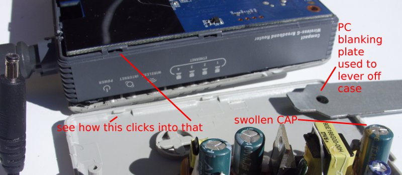
The WRT54GC is not designed to be undone but you can if you don’t care about cosmetic damage. You must remove the bottom first by working your way around with a flat blade (not sharp – I used a blanking plate from the back of a desktop PC case) and popping in the plastic tabs. There are 3 tabs on the ethernet plug side, three on the aerial side, 2 on the front (middle and to right) and 2 on the reset flap side (left and right). There may be a correct tool inside the Linksys factory but I don’t know what this is – expect to break some of the tiny plastic tabs. With the bottom off then the PCB is held on by 3 screws to the top of the case. That’s it – not much to see.

Pulled apart Linksys WRTG54GC and PSU

Actually a PSU problem

Later I rechecked the PSU unplugged and it was down to 1.7 volts. What ? OK definitely a faulty PSU. I found a close equivalent of a 4.5 V PSU from a Belkin wifi repeater which had the same DC plug size and used that on the Linksys and the Linksys device came to life. Oh great so after all that it was just the PSU (which I didn’t have any 5V spares to test with).

Pulling part the Power Supply adapter

So given I had gone so far I decided to see what was inside the Linksys PSU as well and why it failed in such an odd way. These are small sealed units – they are not supposed to be opened. Used a flat-blade screwdriver and hammer to pop the cover off (you can see the insides at the bottom of the picture above) and the fault is obvious – a swollen electrolytic, a TEAPO 1000uF 10V capacitor on the output part of the PSU. Manufacturing date is (as a guess) 09/08 ? ESR in circuit says 1.4 – should be less than 0.1.

Replaced with a spare capacitor I had lying around that was cannibalised from another device (I think an old CDROM drive) and now the PSU has a 5.2 VDC level that stays steady and, more importantly, I plugged it into the re-assembled Linksys router and it all works – blinking lights. I’ll keep it powered up for while to make sure it is stable.

I will buy a new PSU for the client to use with their Linksys so I can get back my spare wifi router. I don’t want to use this repaired PSU at a client site as it is unwise given I’ve broken the PSU case open and though I’ll glue it back again it won’t be as strong a seal as the manufacturer molding. I will keep this repaired PSU as a spare for any future testing though.

http://No.More.gTLD.Please.ICANN/

We do not agree with the ICANN program of allocating new (generic) gTLD.  Their claim that the “expansion of the generic top-level domain (gTLD) space will allow for a greater degree of innovation and choice. ” is, in our view in a word, nonsense.

An existing brand will already have their BRAND plus .COM, .NET and .ORG gTLD. The innovation and choice has already settled at that second level.

A small startup won’t be able to afford to run or own a .BRAND gTLD but must make do with the existing  .COM and other gTLD or ccTLD space. You would be a moron to come up with a great new name and go ahead with your branding without getting the  .COM even if ICANN go ahead with their plans. Your ability to spend a vast amount of money and get a new gTLD isn’t going to make the fact that if you don’t have the .COM then you are still doomed to try a reverse domain name hijack or throw lots of money at the existing .COM owner to grab that too. So much for your choice.

“Innvovation” and “choice” is an application layer problem.  It is not a network problem. ICANN need to go back to school with a wall chart of the ISO 7-layer model if they think that semantically overloading the DNS is a way to “Innovation” and “choice”.

For the past 10 years of the ICANN existence there are basically two problems that ICANN should be focusing on with all their hearts, minds and our money and that is the exhaustion of the IPv4 address space (i.e. IPv6) and the security of the DNS infrastructure (i.e. DNSSEC). Given IPv4 has started to exhaust but many ISP are only in beta programs for IPv6 then we’ll leave you to make a call as to how successful that has been.

We, the existing domain name owners, all pay the ICANN money as a levy on our gTLD domain names that we buy, so we all have a right to complain about what they are doing. Like many domain name owners  we’ve accumulated the main top level domains for our own company, Open Mutual Limited, but being a small company we have ignored the ccTLD and the more esoteric gTLD. With the new ICANN plans we’ll be looking at potentially many hundreds of new gTLD which will segment the domain name space into a vast number of silos and the further out you go from the traditional .COM then these new gTLD seem to get progressively more expensive to buy (if existing .info, .biz or .xxx are anything to go by).

If we wanted to semantically overload our domain names for application reasons then we do this at the 3rd level i.e. http://idea.openmutual.com. Our customers would always go to the existing domain name and then at an application level we would route them to the 3rd level domain and in all probability this would be done behind the scenes without the customer even knowing this domain name existed.

At a company level we would not be able to afford a new gTLD of http://openmutual.idea/ or http://idea.openmutual/and neither would 99.9% of the rest of the world and neither would this be the focus of any startups unless those startups were just in the business of allocating domain names. I fail to see where the innovation and choice is in filling out the ICANN forms to be just another registry for just another gTLD.

http://No.More.gTLD.Please.ICANN/

GNU wget missing libeay32.dll on new install on Windows

When you use the command line wget for the first time on a Windows XP machine (and probably others – Vista and 7 ) you might get an error message,

Unable To Locate Component
This application has failed to start because LIBEAY32.DLL
was not found. Re-installing the application may fix this problem.

On a new Windows installation you may have installed wget but the problem is that wget32 needs other library files (libeay32.dll, libintl3.dll, libiconv2.dll and libssl32.dll) and these are not usually on a new Windows machine.

What you probably forgot to do with installing wget is install the dependencies !

Go to the GNU Wget binary download site for Windows and get the “Dependencies” ZIP file. Unpack the 4 DLLs from that /bin/ directory in the ZIP file into the same /bin/ directory where you have the wget.exe.

Wget will now work.

I use wget to download large ISO files from places that don’t have obvious bittorrent links e.g. Sourceforge. I do this because wget is more reliable than the browser in handling partial downloads i.e. where the Internet link has been closed and you have received only part of the file. Wget allows you to restart the download where it last finished.


Aprilia Leonardo 125 head light switch repair

And now for something completely different but this uses electricity so thought I would add it here; Front lights stopped working on a 2001 Aprilia Leonardo 125 (ST). The fix worked out to be rather easy: There is no relay with this – it is wired from an ignition supply through the right-hand light selector to the left-hand high/low beam switch and then down to the headlights.

To test this you need to remove the back of the display console like you would do to top up the brake fluid (i.e. you would have to remove your windsheild/windscreen as well if you have one).

If you look inside where the right-hand side controls are you have the starter motor switch on the bottom and the light selector above it. The Light selector is in two parts each with 3 pins; the top of the switch is the main lights and the bottom is the back and front side light (which is a small light in the middle of the front light cluster). For the main beam section it has a green supply wire and a black/yellow wire that goes across to the left hand side high-low beam selector. There will be regional variations with this switch but they should function the same.

With the ignition on then you should get 12 Volts on the green supply wires and when the switch is moved to the on position then the 12V should appear on the other pin.

With mine it wasn’t so I remove the switch; to do this there are on the back, a tab on each side of the switch towards the top which you need  small flat screwdriver to push in and so can now push the switch out. The switch comes out and up as a complete assembly.

There may be newer models that are all sealed but with mine the dismantle was easy – on the back of the switch there is a section that pops down and you can now take out the inner red spacer and then slide out the switch lever. My fault was obvious; over time the switch has heated up and the plastic of the switch has melted and has stopped the switch contact from staying in contact. Cleaned out plastic with a knife, bit of plain grease, reassembled, tested and installed and the lights worked.

Second hand (or even new) this part is quite cheap so why bother with a repair ? The problem is that the bike isn’t street legal without lights so if it can be fixed without having to hunt for replacement parts then your downtime is reduced.  While you are at it, if it hasn’t been done, you can do your brake maintenance given you have the master-cylinders exposed.