Side effects of fault voltage regulator on Aprilia Leonardo 125 ST

About 6 months ago the voltage regulator failed on my Aprilia Leonardo 125 ST (2001) but I’m now confident that it was playing up before that time.

I’ve had the bike for 3 years with no problems and then the battery failed earlier this year. I assumed it was just old and so bought a new battery and it was working well for a few weeks until one day I came home and smelt boiling acid. This brought back memories as I’ve worked on very large battery banks (up to 10,000 AH at 50VDC for TELCOs) and so recognised that acrid smell of heavily working batteries.

I carefully popped the seat open and removed the battery cover. Acid steam was venting. I got water, goggles and gloves and unbolted the battery and removed it. Beh ! brand new battery cooked. The next day I re-charged the battery, put it back in the bike and it seemed OK but I doubt it would last.  Everything seemed fine though with an expected battery voltage.

I’ll jump to the end and what was happening was that the voltage regulator was failing but only intermittently. It eventually failed long enough for me to see a reading of 17 volts on the battery terminals !

The side effect of this though was the following…

  • the headlights would run normally and then would run brighter. I drive with the lights on all the time and so the higher voltage meant that they drew more current and this both contributed to them blowing faster and drawing more current through the light switch. I’d noticed this but never really thought much of it. I’ve blogged about the switch failure here.
  • when the battery failed then I had trouble starting the bike and so this meant more cranking. This probably contributed to increased wear on the starter brushes. I blogged this here.
  • the increased voltage meant an increase in current overall for all systems and so this probably helped the ignition switch to also slowly unsolder itself. I’ve blogged this here.

So: if you notice your lights altering in intensity a bit, or the radiator fan changing sound/speed, or certainly if  the battery is getting hot then you must check the voltage on the battery terminals is precisely as expected (which is usually under 14 Volts).

With intermittent problems there is not really much you can do because there are no engine management system over-volt indicators on such an old scooter so you just have to be alert for these subtle indications in the lights or fan sound before you end up with a boiled battery and a whole pile of other electrical problems.

The voltage regulator is the same across a wide range of Aprilia bikes so the part can be bought fairly cheaply second hand or you can invest in a new one. Once I put a new regulator in then I replaced the battery as the cooked one couldn’t be relied on.

 

Dead spot on Aprilia Leonardo starter motor

Another electrical problem but I found out how to prove this and discovered a very useful get-you-home fix; The problem is that I tried to start the bike but just heard the click of the starter relay.

The quick answer to what I eventually found was that the brushes in the starter motor had worn down to the last little bit (on 43,000 kms). Minor variations in the commutator meant that the brush did not touch at one point. It had a “dead spot”.

I discovered a get-you-home fix; Turn on the ignition and push the starter switch then bounce hard up and down on the seat (like you are testing the shocks). This rotates the starter motor around a little to step over the dead spot if it is a dead spot and it may start – it did for me.

If that fixes your problem then get to a garage or home in one go because what it means is probably that your starter bushes are down to the last bit of metal and this will fail to start again and the bouncing on the seat trick may not work.

As I mentioned I accidentally discovered the temporary fix but in proving what was actually wrong I also worked out a test routine as it could be one of 4 different things,

  1. the relay contacts not working
  2. no 12VDC +ve in
  3. no Earth
  4. problem with starter motor

When you push the ignition switch then you should hear a solid click of the relay every time you push in the switch. The relay is located under the right hand side of the seat and the contacts are visible through an air vent just above the right hand inspection opening. They are two large lugs.

If you don’t hear this click then you have a problem with the relay circuit from the starter switch on the handlebar to the relay. You’ll have to trace this out with a multimeter though if you are on the road and don’t have a multimeter then I would,

  • Check fuses are OK
  • check wiring connections to relay and to starter switch look ok (no corrosion)
  • check starter switch making contact (if you can you could try to prove by shorting the switch contacts with a wire)

If the relay is making a click and if you don’t have a multimeter you can test (1) and (4) by shorting the contacts of the relay with a bit of wire. Don’t short to frame – just between the contacts. One side is always 12V +ve and the other connects through the starter motor to the engine earth. With the ignition OFF if you try and short the relay contacts and they do NOT spark then the starter motor (or Earth or +ve supply) probably has a problem. If they DO spark then the relay probably has a problem. Take care with shorting this obviously.

If you do have a multimeter then testing is very easy. You should see 12 volts on one side of the relay all the time and when you push the starter switch then it should appear on the other side.  If it does not then the relay is probably faulty.

If you do see the relay working then the 12 volt supply goes to the starter motor via the heavy cable (then through the motor to the earth). With the ignition off then if you measure the resistance from the battery -ve/Earth post to the starter relay lug that goes to the starter motor (not the other side of the relay as that is always live !) then you should see less than an ohm e.g. only half an ohm (0.5 Ω) – basically a near short as the starter motor is about 500 watts so at 12 Volts that means about 0.3 ohms. If you see a high reading (more than an ohm) or an open circuit then check that the case of the starter motor is low resistance (it should be at earth) and then check that the lug into starter motor is low resistance. The starter case will be corroded a bit so make sure you are touching actual metal.

If your finding is that the starter motor has a high resistance through it then it is probably the brushes. The starter motor is easy to remove though it will clash with the carburettor so not much wiggle room. The starter motor is also easy to pull apart and if it is a worn brush then this is obvious. You may be able to get a few more starts by bending the brush housing a bit but the brush wire is what will stop you in the end. If you do bend the housing to gain some starts then you can test the motor on the bench by checking the resistance stays low between the case and terminal lug whilst you slowly rotate the motor by hand one whole revolution. It should stay low ohms at every point.

If it is an original Mitsui starter motor then I don’t believe that you can get replacement brushes assembly though an auto electrician may know of an equivalent brush part. AFAIKS the starter motor is the same for all  Leonardo 125 and 150 models for all years (96-04) and for some other models that use the Rotax Type 120/154 (120S-154S) engine (e.g. Scarabeo 125/150/200 from 99-03 and also the BMW C1 125/200 from 00-03 ). The OEM Aprilia starter motors are very expensive – but there are much cheaper “Economical” or equivalent motors that are made that are a 1/4 of the price new. Unless you know the kilometres of a second hand bike or you can actually see the bushes to see how much is left on them I wouldn’t buy a second hand starter motor.


Fixing Linksys WRT54GC – actually the PSU

Client of mine had his trading systems disconnect from the internet and his local lan device, a Cisco Linksys WRT54GC V3 – it had no lights.

On-site I checked the Linksys PSU ( a small 5V 1A adapter) with a multimeter and it showed (used a paper-clip to poke into the hole) about 4.7 volts. Which seemed OK at the time. So swapped out the client device for a spare non-Linksys Wifi router and the internet was back for client.

Got the Linksys back home and then popped the cover (see below) and powered it up. The supply pin dropped to 4.2 volts and there was only 1.5 volts on the memory chip (an ETRON SDRAM chip with pin 1 and 54 as the VDD and VSS) rather than the expected 3 volts or so.

Pulling apart the WRT54GC

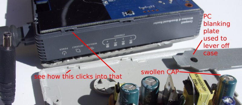
The WRT54GC is not designed to be undone but you can if you don’t care about cosmetic damage. You must remove the bottom first by working your way around with a flat blade (not sharp – I used a blanking plate from the back of a desktop PC case) and popping in the plastic tabs. There are 3 tabs on the ethernet plug side, three on the aerial side, 2 on the front (middle and to right) and 2 on the reset flap side (left and right). There may be a correct tool inside the Linksys factory but I don’t know what this is – expect to break some of the tiny plastic tabs. With the bottom off then the PCB is held on by 3 screws to the top of the case. That’s it – not much to see.

Pulled apart Linksys WRTG54GC and PSU

Actually a PSU problem

Later I rechecked the PSU unplugged and it was down to 1.7 volts. What ? OK definitely a faulty PSU. I found a close equivalent of a 4.5 V PSU from a Belkin wifi repeater which had the same DC plug size and used that on the Linksys and the Linksys device came to life. Oh great so after all that it was just the PSU (which I didn’t have any 5V spares to test with).

Pulling part the Power Supply adapter

So given I had gone so far I decided to see what was inside the Linksys PSU as well and why it failed in such an odd way. These are small sealed units – they are not supposed to be opened. Used a flat-blade screwdriver and hammer to pop the cover off (you can see the insides at the bottom of the picture above) and the fault is obvious – a swollen electrolytic, a TEAPO 1000uF 10V capacitor on the output part of the PSU. Manufacturing date is (as a guess) 09/08 ? ESR in circuit says 1.4 – should be less than 0.1.

Replaced with a spare capacitor I had lying around that was cannibalised from another device (I think an old CDROM drive) and now the PSU has a 5.2 VDC level that stays steady and, more importantly, I plugged it into the re-assembled Linksys router and it all works – blinking lights. I’ll keep it powered up for while to make sure it is stable.

I will buy a new PSU for the client to use with their Linksys so I can get back my spare wifi router. I don’t want to use this repaired PSU at a client site as it is unwise given I’ve broken the PSU case open and though I’ll glue it back again it won’t be as strong a seal as the manufacturer molding. I will keep this repaired PSU as a spare for any future testing though.

Aprilia Leonardo 125 head light switch repair

And now for something completely different but this uses electricity so thought I would add it here; Front lights stopped working on a 2001 Aprilia Leonardo 125 (ST). The fix worked out to be rather easy: There is no relay with this – it is wired from an ignition supply through the right-hand light selector to the left-hand high/low beam switch and then down to the headlights.

To test this you need to remove the back of the display console like you would do to top up the brake fluid (i.e. you would have to remove your windsheild/windscreen as well if you have one).

If you look inside where the right-hand side controls are you have the starter motor switch on the bottom and the light selector above it. The Light selector is in two parts each with 3 pins; the top of the switch is the main lights and the bottom is the back and front side light (which is a small light in the middle of the front light cluster). For the main beam section it has a green supply wire and a black/yellow wire that goes across to the left hand side high-low beam selector. There will be regional variations with this switch but they should function the same.

With the ignition on then you should get 12 Volts on the green supply wires and when the switch is moved to the on position then the 12V should appear on the other pin.

With mine it wasn’t so I remove the switch; to do this there are on the back, a tab on each side of the switch towards the top which you need  small flat screwdriver to push in and so can now push the switch out. The switch comes out and up as a complete assembly.

There may be newer models that are all sealed but with mine the dismantle was easy – on the back of the switch there is a section that pops down and you can now take out the inner red spacer and then slide out the switch lever. My fault was obvious; over time the switch has heated up and the plastic of the switch has melted and has stopped the switch contact from staying in contact. Cleaned out plastic with a knife, bit of plain grease, reassembled, tested and installed and the lights worked.

Second hand (or even new) this part is quite cheap so why bother with a repair ? The problem is that the bike isn’t street legal without lights so if it can be fixed without having to hunt for replacement parts then your downtime is reduced.  While you are at it, if it hasn’t been done, you can do your brake maintenance given you have the master-cylinders exposed.

Epson DX5000 printing borderless – bogus paper jam error

This is a long story…..We have an Epson DX5000 with a CISS that was found at the trash with the CISS intact but the CISS ink feed tube guide/holder (that comes with your CISS kit) was broken off. Out of habit I collect printers for their motors and other parts but this is the first time I’ve seen an abandoned CISS (4 colour). I just had to see if I could make it work or, at least, re-use the CISS in another printer. It seemed to have around 50ml in each reservoir so a bit messy – but it was raining so the ink washed off (it is dye ink).

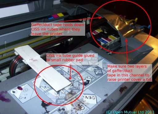
Without this little plastic guide in place the CISS ink feed tubes would drop and collide with the print carriage.  From experimenting with this I found you have to get this near perfect alignment else it just clips the print carriage as it zips back and forth. The plastic shrouds on the print carriage almost look designed to interfere with foreign objects like the CISS ink feed tubes. With the DX5000 then there is so little gap the scanner/printer cover pushes down and can hit this  ink feed tube guide and thus push it into the path of the print carriage.

Image showing position of tube guide and where to use gaffer/duct tape

Details of tube retainer position and use of gaffer/tape.

The fix I found is very easy. For the CISS ink feed tube guide I superglued it to a thin 1.5mm by 20mm x 20mm bit of foam rubber similar to what you use on the base of equipment as rubber feet and then glued this in place. This made it slightly more proud and so had a better tolerance in clearing the print carriage.

I then used gaffer/duct tape on the ink feed tubes where the tubes leave the printer. This keeps the tubes in place and especially keeps the printer cover just a little up and out of the way thus stopping it from pushing the CISS ink tube guide that I had glued in down into the print carriage.

I bleed the many air bubbles by lifting the CISS ink reservoirs up high. You never normally do this – the ink reservoirs must always normally stay on the same level as the base of the printer else they will siphon out. After a week it settled down and we’ve found it perfect for high-volume draft work such as book drafts. The CISS cartridges have auto-reset chips in them so when the ink levels are low then the chips reset themselves back to full. So that is the history of that printer.

Now the odd problem of the title: we have found is that if you want to do borderless then you must select Epson paper stock. If you say “plain paper” in the print driver then it says that this option is not available for this media and then resets the borderless setting off.

If you specify the Epson paper then the number of sizes in the media size option reduces and importantly for us for our test, the A5 disappeared as, I can guess, Epson do not do A5 card intended for borderless printing. If you try picking A4, but load your non-Epson A5 then it starts to load the paper but then it says “Paper Jam” though it provides an “Eject” button and that works fine so there isn’t really a paper jam per se.

I know this is true because if I pick plain paper A4 and load A5 stock landscape and only print a (normal with border) image then it works perfectly and prints on the A5 and then tractors the paper out without complaining that you told it was A4 but only fed A5.

The paper jam that it says that it has when you try this trick with non-Epson paper on borderless seems to be some catch-all complaint about the paper stock that it detects before it starts up to print. There is some kind of sensing logic at the start of the job when it runs the print head back and forth before it has started printing the image. Bit annoying as we wanted to print borderless on A5 scored card stock and can only do with-border.


Success through experience – the hard way.

If you’ve looked at the fixes I’ve listed here it seems that the fault and the solution are found without any problems and that there is a straight line between these two.

Not always so – I was able to fix the Acer flat panel screen because earlier in the year I had worked on the internals of two other screens (both trashware) without success; one was a generic 15in and one was an ex-medical system 17inch touch screen that I so want to fix. So by now I already had many hours of experience of dismantling, measuring voltages and re-assembling these kind of screens without injuring myself or damaging the parts but with much disappointment.

My experience on these found items means that I approached the most recent find with a lot more confidence and speed of dismantling and re-assembling and it was successful. Ultimately this knowledge all goes to benefit work I do for customers too.

Easy repair of an Acer AL1721 flat panel (trashware)

Walked some trash to the rubbish bins and saw a 17inch Acer AL1721 flat panel screen (for a PC)  dumped at the bins. Don’t get to see many flat panels. Seemed to not have a cracked screen so I just had to take this back home.

At home I used a spare 5AMP 12 V DC power pack (centre positive) I had similar to what is used for CCTV cameras and it kind of worked but screen blanked out when DC plug was wiggled.

This had to be easy to fix so I unscrewed the screen back (4 x small black screws and 4 x larger plated screws under the stand mount covers) and then popped off the front bezel screen surround and removed the back (take care to un-plug the screen controls plug).

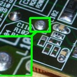
The PSU is slightly different from other screens and is an all-in one with the backlight high volt supply and the logic supply together on the same PCB. The fault was easy to find though – there is a choke on the DC input on the PCB and that had a visible dry joint.  I can only assume some contamination on the pin when it was soldered at the factory.

Dry Joint on PSU PCB

Dry Joint on PSU PCB

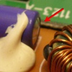
I solder-sucked and scraped the pin with a knife edge to the copper on the pin and then re-soldered. There was also a 470uF 16VDC electrolytic that was swollen (HERMEI brand) though my ESR meter did not show a problem. I replaced it anyway given it was swollen (the spare capacitor was cannibalized from the power section of an old CDROM drive so this fix cost me nothing).

Swollen Capacitor on AL 1721 PSU PCB

Swollen Capacitor on AL 1721 PSU PCB


It works; stable at 1280×1024 75Hz on a GNU/Linux server running Ubuntu 10.10 with on-board ATI Radeon 3000 graphics (ASUS M4A78LT-M LE motherboard).

International Amazon Kindle not charging from USB ?

A client of ours had got a Kindle recently and seemed happy with it but the batteries kept going flat.  I checked and it seemed to be charging fine so I dug a bit deeper and this what I found.

The PC is a brand new laptop running Windows 7 Home Premium –  I know as I re-installed that as English a few weeks ago. The power management was left as the default of Balanced.

The quirk with this is that they leave the Kindle plugged in when they go out but the Balanced power setting on Windows 7 by default shuts the PC down in 30 minutes (when on mains) when idle.

The Kindle needs 4 – 6 hours to charge thus it will never really charge unless you stop the Laptop from going into power save mode. I changed the Balanced on-mains power shutdown period to 4 hours to at least give the Kindle a chance to get a charge.

I imagine that other people have had this without really thinking about what is happening.


HIgh CPU with system process on Windows XP ?

The system process (not the system idle) can go to high CPU use. To narrow down what is causing this you need to narrow it down to a thread that system is managing.

Do this by downloading the System process explorer from Microsoft. Download and run the procexp.exe program that the .zip file contains. click “run” and then “run” again on the dialogs (you basically run this program – not install it).

It runs and display a more complex system overview than the taskmanager. Sort on the “Process” column and then find and right-click the “System” process and pick “Properties”.

You can now pick the “Thread” tab and sort on the CPU column and find out which driver is running the high CPU. To see where and what version this file is click the line e.g. amdk8.sys and then click the “module” button. It will pop up a normal File Properties dialog box.

You have all you need now to search technical help sites or your hardware provider to see if there is updated software for this driver: searching for “amdk8.sys high cpu” is a lot better than searching for just “system high cpu”


Taskmgr.exe at 100% CPU ?

On older laptops you may start seeing this problem. It seems to be caused by the CPU going into a protective shutdown whereby it reduces the clock rate to a small amount (seen on a Celeron-based IBM R31 laptop).

In Task Manager (ctrl+alt+del) then you will see 100% CPU with taskmgr.exe consuming a lot of this.

The laptop will run very slow and if you can get CPU-Z running it will show up a low core speed.

The only temporary fix is to reboot (sometimes hard shutdown by push-and-hold the power button for 10 seconds) but if the machine has cooling problems then this is not going away and you’re going to have to investigate deeper into the machine.


Old Acer 1360 Laptop hot hot hot….

Reinstalling a very old laptop (Aspire 1360) with its Windows XP Home and it halts just like a power shutdown. Trouble was that when trying an Ubuntu install then that worked. Odd.

Redid the WinXP install and it failed – retried the Ubuntu install and finally got an error message that shot off the screen but it was useful – overtemperature (80 Deg C) shutting down. The ACER BIOS (v1.09) doesn’t actually show the hardware sensors – gee that’s useful.

Interestingly I had also tried to start a Window Vista install and I got a “STOP: c000021a (Fatal System Error)” Error

I’d already cleaned out a whole ecosystem of colonies of “dust bunnies” from this machine but looks like something else has a problem. So took off the plastic cover with the feature buttons on on the top of the laptop to see if there was anything else and then tried the heatsink screws – one seemed looser than the others.

So far vacuum, tighten heatsink screws, remove dust and cat hair and swapped around memory chip positions seems to have done the trick on the install. I now have it back as a Windows XP with dual-boot to Ubuntu 11.04.


ACER 1360 BIOS 1.15 Model ID check error

I’m recovering a heat-damaged Acer Aspire 1360 and I wanted to update the BIOS. I went to the Acer web site and found the 1.15 version. This didn’t install but failed with a “Model ID check error”.

I re-downloaded the file from a different Acer site (UK and US) but same problem. I then tried the Acer FTP site,

ftp://ftp.acer-euro.com/notebook/aspire_1360/

and sure enough I found the problem.

The old BIOS files had two models in them, the 1520 and the 1360 but the version 1.15 only has the Acer Aspire 1520 files.

So AFAIKS you can only flash to version 1.11 of the BIOS (this gives 64 bit support).